Utility box template

Inactive Publication Date: 2005-01-18
DIMAURO ROBERT T
View PDF19 Cites 28 Cited by
  • Summary
  • Abstract
  • Description
  • Claims
  • Application Information

AI Technical Summary

Benefits of technology

It is also an object of the invention to provide a template which facilitates positioning and cutting an opening in a wall or ceiling for installing a utility box.

Problems solved by technology

Often, however, it is necessary to add utility boxes after the construction has been completed.
The devices that are used for aligning, or positioning, utility boxes during new construction generally require ready access to the building framework and are therefore of little assistance in remodeling applications.
This method, however, is difficult to carry out without damaging the gypsum board or producing an installation that is correctly positioned, with the side edges of the box being in a straight vertical orientation and properly aligned with the side of the framework.
Many of the problems associated with improper positioning of the box stem from the difficulties associated with the use of a paper template to mark the outline of the location to be cut from the gypsum board to install the box.
This is difficult to do, since the top edge of some utility boxes are not regularly shaped and the level interferes with the tracing.
In many cases, the installer merely “eyeballs” the correct position, resulting in irregularly-positioned utility boxes.

Method used


Image

  • Utility box template
  • Utility box template
  • Utility box template

Examples


Embodiment Construction

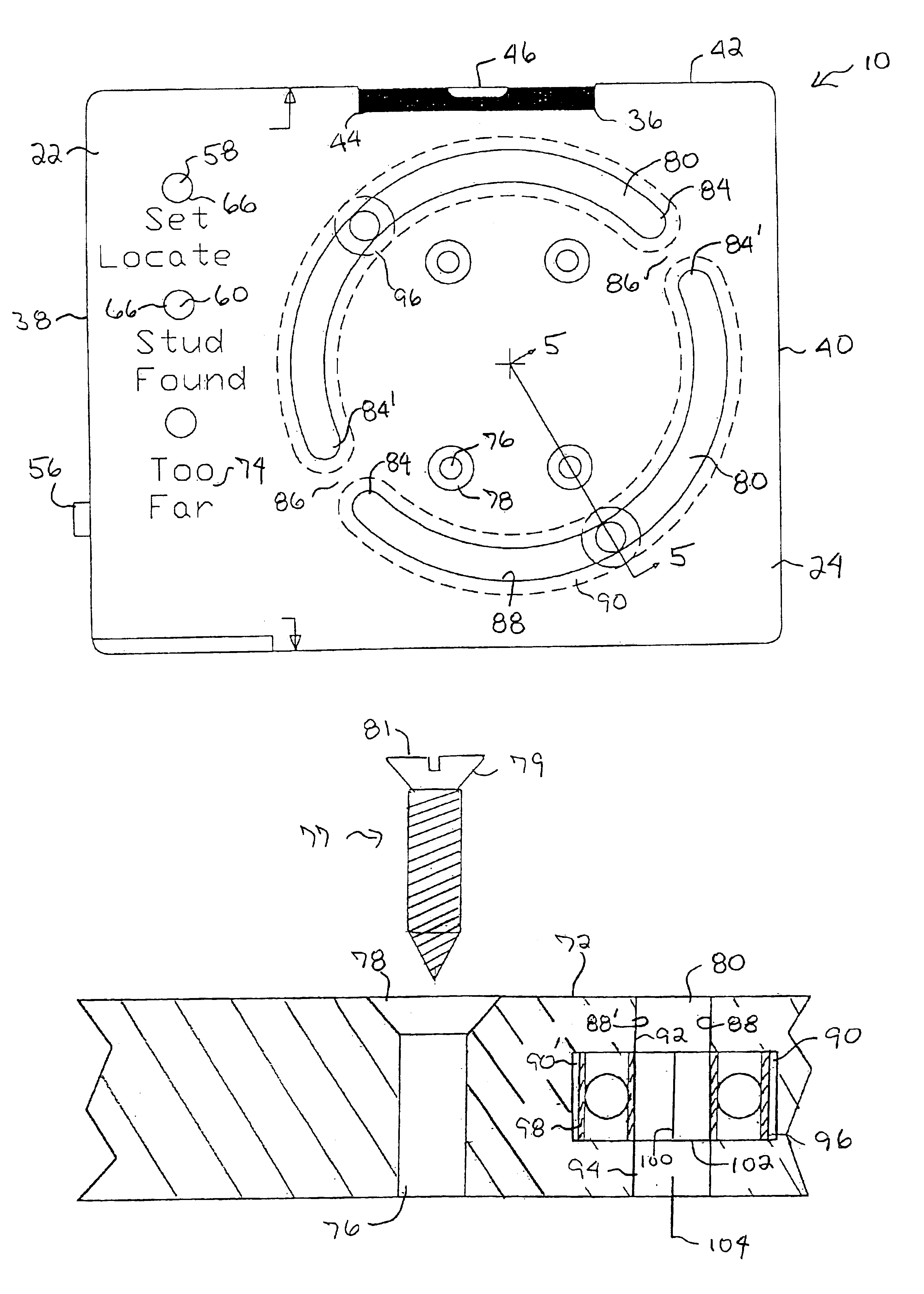
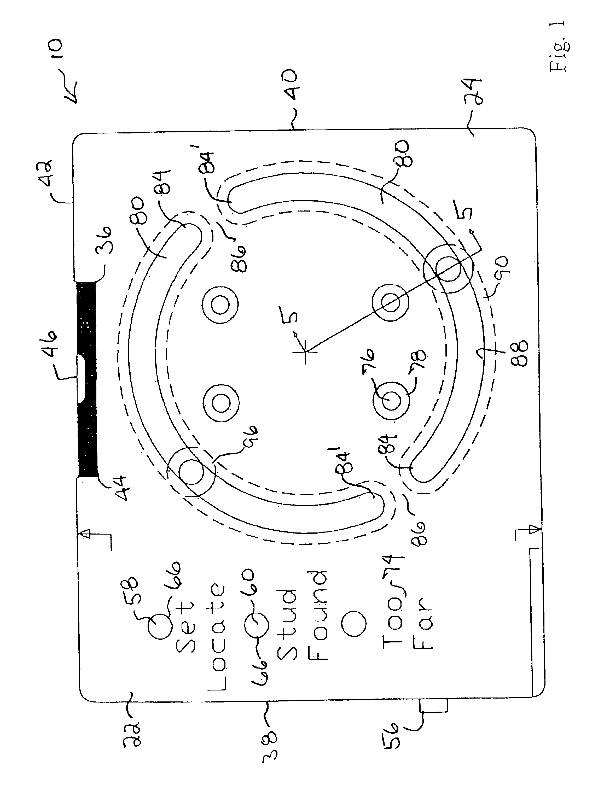
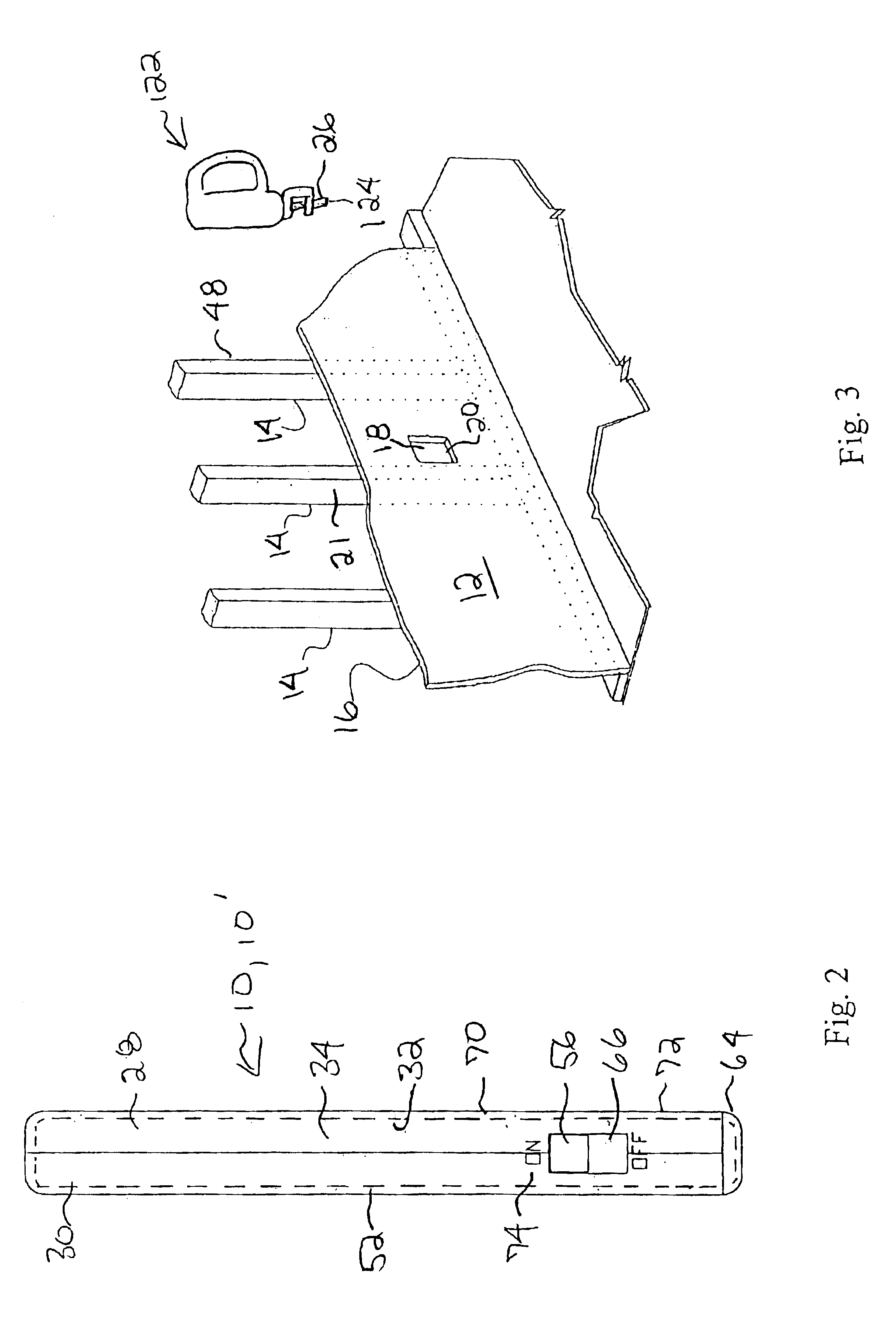
With reference to FIG. 3, building walls 12 are typically formed of a framework of wood or metal studs 14 which is covered by materials 16 such as drywall sheets, paneling, or a plaster base such as lathe or wire mesh. Wiring (e.g. electrical power, phone lines, speaker wire, coaxial cable, etc.) routed through the framework is terminated at electrical boxes mounted to the framework studs 14. Plumbing routed through the framework may also be terminated at a modular connection or box. When such utility boxes are installed after the covering material 16 is already mounted on the studs 14, a mounting site 18 must be located and an installation opening 20 cut in the covering material 16 at the mounting site 18. For a side-mounted utility box (i.e. a utility box which is to be mounted to the side 21 of one of the studs 14), the mounting site 18 and installation opening 20 may be located and cut utilizing a utility box template 10 in accordance with the present invention.

The utility box t...


PUM

PropertyMeasurementUnit
Shapeaaaaaaaaaa
Levelaaaaaaaaaa

Abstract

A utility box template, for installing a utility box in a building wall or ceiling formed of a framework of studs overlaid by covering material, which comprises a one-piece, unitary plate including a locator portion and a guide portion. A stud finder, for locating the studs, is mounted in the locator portion. A cutting guide, for guiding a cutting device for cutting an installation opening in the covering material, is mounted in the guide portion.

Description

BACKGROUND OF THE INVENTIONThis invention relates generally to a tool for placing and marking the position of a utility box in a wall, such as drywall, floor, or ceiling. A “utility box” is a device intended to be accessible through an opening in a wall such as electrical service boxes for outlets and switches, cable television and telephone connections, plumbing fixtures such as modular clothes washer water connections, and lighting fixtures such as recessed lighting cans. More particularly, the present invention relates to a device and method for marking the location and support for an utility box on wall and for creating the aperture in the wall for receiving the utility box.During the constructing of a building, walls are typically formed by initially erecting a framework including wood or metal studs. Rough plumbing and electrical wiring is then routed through the framework. The wiring is terminated at electrical boxes mounted to the framework studs. Phone lines, speaker wire a...

Claims


Application Information

Patent Timeline
IPC IPC(8): G01B5/00H02G1/00
CPCH02G1/00H02G2200/30Y10S33/10B25H7/02Y10T83/8763
Inventor DIMAURO, ROBERT T.
Owner DIMAURO ROBERT T
Why Eureka
Try Eureka