Vertebral endplate chisel

a technology of vertebral endplates and chisels, which is applied in the field of posterior lumbar interbody fusion, can solve the problems of increasing the extent of disk space collapse, disc space in which the disc sits, and implants that do not typically fit congruently into the distracted disk spa

Inactive Publication Date: 2005-01-11
DEPUY ACROMED INC
View PDF31 Cites 149 Cited by
  • Summary
  • Abstract
  • Description
  • Claims
  • Application Information

AI Technical Summary

Benefits of technology

Lastly, since the guide of the inventive device is integrally connected to the base, shaving is performed by simply precisely locating the shaving portions at the desired depth of

Problems solved by technology

However, the pathophysiology of an intervertebral disc is such that the disc space in which the disc sits is typically collapsed (e.g., 30-50% of the time) prior to disc removal.
Once the natural disc is removed (but prior to implant insertion), the annulus and soft tissue surrounding the disk space tend to force the adjacent vertebrae to come even closer together, thereby increasing the extent of disk space collapse.
However, since the geometry of the disk space varies from patient to patient, and the implants are typically manufactured in only a few shapes, the implants do not typically fit congruently into the distracted disk space.
However, the current PLIF procedure for forming substantially rectangular channels in the endplates is a time-consuming three-step process.
In addition, cannulated technology (which protects the internal organs from the rotary cutting devices) is often needed when drilling devices are used, thereby increasing the c

Method used


Image

  • Vertebral endplate chisel
  • Vertebral endplate chisel
  • Vertebral endplate chisel

Examples


example i

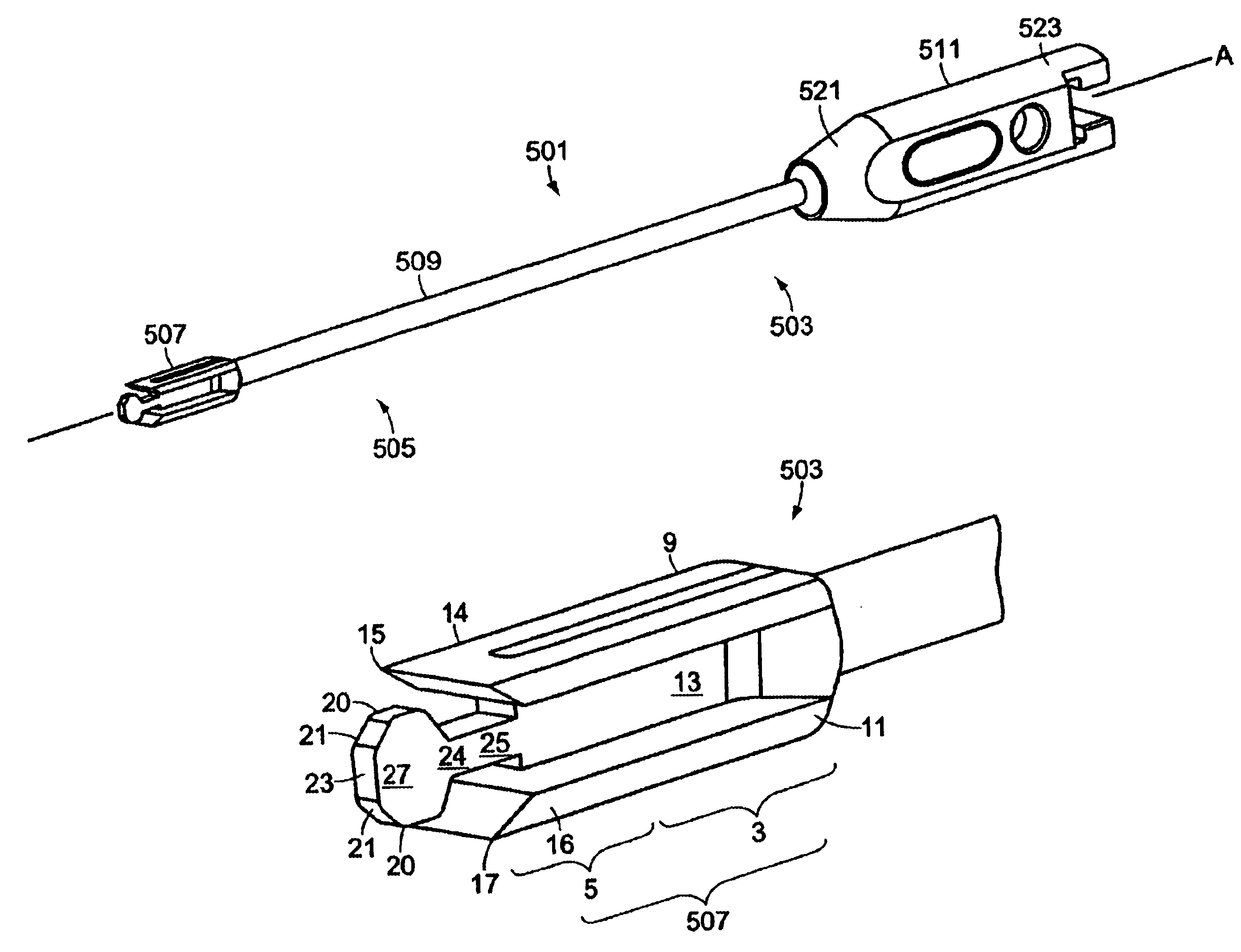
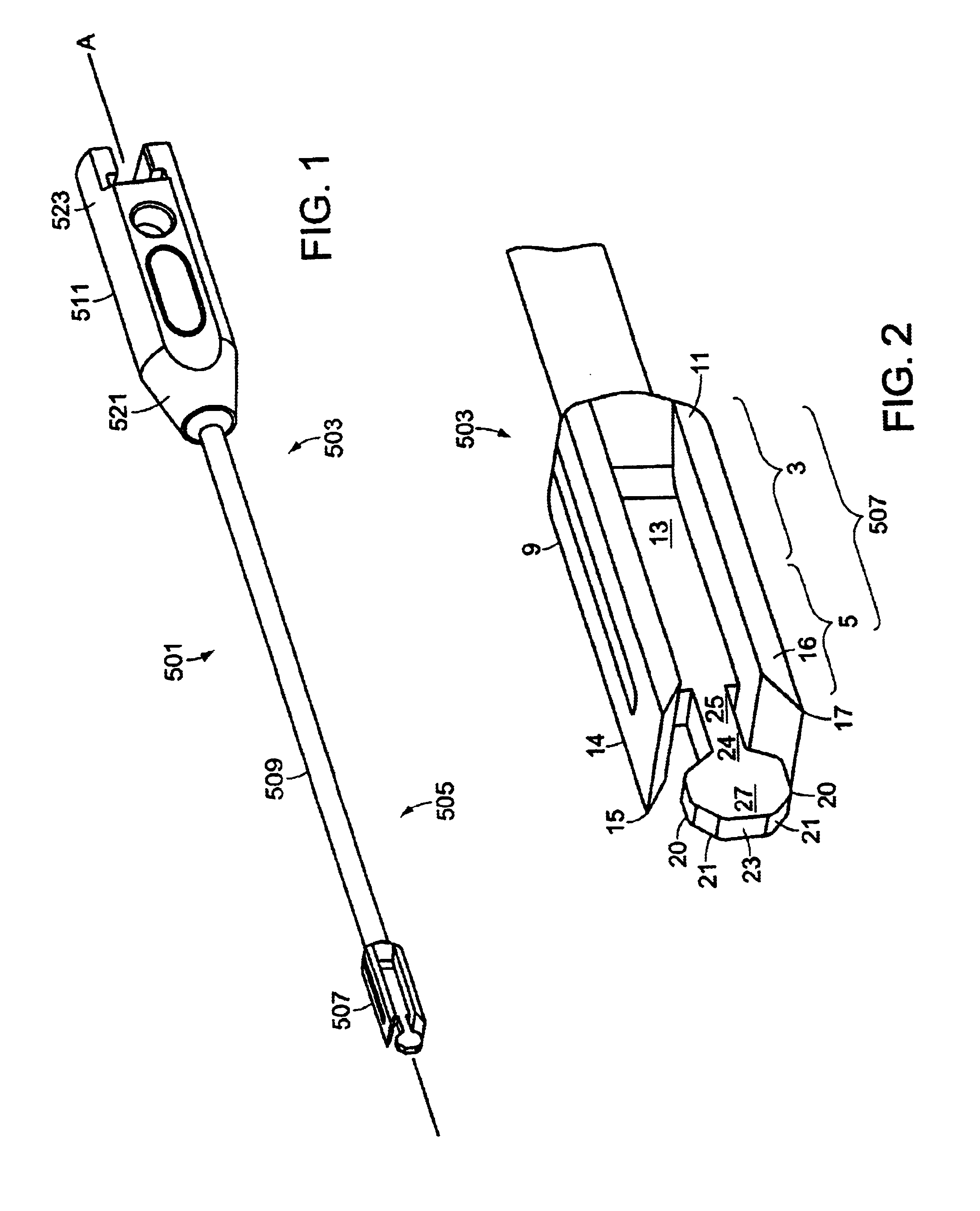
Now referring to FIG. 1, the Box Chisel 1 has a proximal portion 503 and a distal portion 505 formed along its longitudinal axis A. Now referring to FIG. 2, at distal portion 505 is a rectangular base 507, having upper 9, lower 11 and intermediate 13 portions. Upper and lower portions 9 and 11 terminate in distally-extending upper and lower shavers 14,16. Intermediate portion 13 terminates distally in a flat thin guide 24 having a neck portion 25 extending from the intermediate portion 13 and a head portion 27 extending from the neck 25. Head portion 27 includes upper and lower land portions 20, upper and lower tapered portions 21, and a flat leading edge 23 formed by the termination of the tapered portions prior to their convergence. Tips 15, 17 of shavers 14,16 terminate distally before the head portion 27 forms its lands 20.

The overall shape of guide 24 can be described as a pancake-like. Now referring to FIG. 6, in one exemplary sized 9×11 Box Chisel, the height HH of the head (...

example ii

In this embodiment, now referring to FIG. 14, the base 207 of the box chisel 201 has an I-Beam-like section 208. The shavers 214,216 extend from the upper and lower base portions 209,211 and are formed by a height-increasing step 229 from the upper and lower base portions 209,211. The step reduces the stiction of the device. The guide 224 includes a i) neck portion 225 which widens as it extends distally and ii) a thin head portion 227 which has a rounded cross-section terminating in a flat leading edge 223.

example iii

Now referring to FIG. 12, this device includes a head 307 having lands 320 and a bullet-shaped distal section 321. The neck portion 325 of the guide includes both a rod-like section 360 and a widening section 361. The base 307 includes a substantially blocky proximal section 306 and an I-beam-like section 308.


PUM


Abstract

A vertebral endplate chisel having upper and lower shaving portions, and a non-cutting guide integrally connected to and extending between the shaving portions and adapted to center the chisel within the disc space so that equal amounts of bone are removed from each endplate by the shaving portions as the chisel moves through the disc space.

Description

BACKGROUND OF THE INVENTIONThe basic goal of a typical Posterior Lumbar Interbody Fusion (“PLIF”) procedure is to remove a problematic disc, and insert a prosthetic fusion device (such as a cage or a mesh) into the empty disk space created by removal of the natural disc. However, the pathophysiology of an intervertebral disc is such that the disc space in which the disc sits is typically collapsed (e.g., 30-50% of the time) prior to disc removal. Once the natural disc is removed (but prior to implant insertion), the annulus and soft tissue surrounding the disk space tend to force the adjacent vertebrae to come even closer together, thereby increasing the extent of disk space collapse. Since one goal of the surgery is to restore the patient's anatomic disc space to the extent possible, there is a need to spread apart these collapsed vertebrae. In one conventional PLIF procedure, a flat Spreader (which resembles a butter knife) is inserted with a horizontal disposition into the collap...

Claims


Application Information

Patent Timeline
IPC IPC(8): A61B17/16A61B17/17A61B17/56
CPCA61B17/1604A61B17/1671A61B17/1757A61B17/1735
Inventor ROGERS, CHRISTOPHERMALONE, JOHN DANIEL
Owner DEPUY ACROMED INC
Why Eureka
Try Eureka