Surgical sagittal saw and method of using same

Active Publication Date: 2006-01-12
STRYKER CORP
View PDF48 Cites 140 Cited by
  • Summary
  • Abstract
  • Description
  • Claims
  • Application Information

AI Technical Summary

Benefits of technology

[0023] The capture pin reduces the overall size of the cutting guide, which makes it possible to use a cutting guide that is relatively small in size. Further, the cutting guide according to the invention allows greater cutting site visibility of open-face cutting gui

Problems solved by technology

While presently available sagittal saws and complementary cutting guides work reasonably well, there are some noticeable limitations.
One problem associated with the wearing away of this material is that it widens the slot.
Eventually, the slot may become so wide that it no longer serves to precisely define the cut line it is intended to define.
Moreover, the wearing of the material forming the cutting guide generates a fine dust of the material.
This dust inevitably settles on the surgical site at which the procedure is being performed.
Consequently, during the procedure, the surgical personnel are required to spend an appreciable amount of time flushing the site to remove this dust.
One further disadvantage of this blade galling is that same consumes power, and since many sagittal saws are battery powered, the power expended due to the friction caused by the blade galling reduces the overall amount of power the battery has available to power the saw.
Moreover, as a consequence of the saw blade galling against a surface of the cutting guide, and then pulling away from the surface, there is some jerking of the blade.
Also, as an inevitable result of the back-and- forth motion of the blade, the surgical saw invariably vibrates.
Over time, having to so hold the saw steady to overcome this vibration can be significantly mentally and phy

Method used


Image

  • Surgical sagittal saw and method of using same
  • Surgical sagittal saw and method of using same
  • Surgical sagittal saw and method of using same

Examples


Embodiment Construction

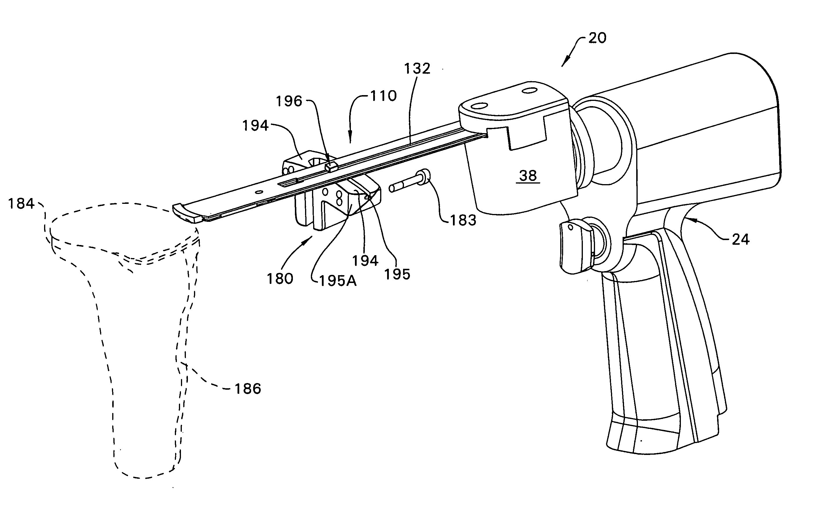
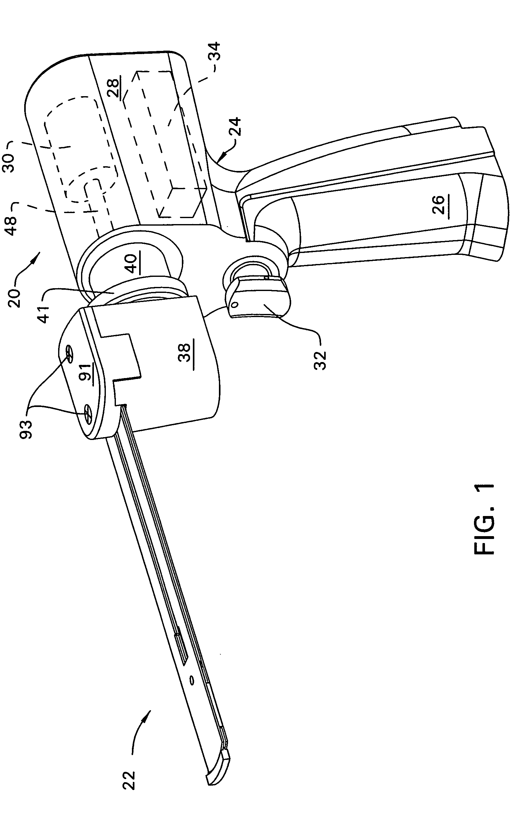
[0051]FIG. 1 illustrates a surgical saw 20 and complementary blade assembly 22 of this invention. Saw 20 includes a handpiece 24 that functions as the body of the saw. The handpiece 24 is shaped to have a handgrip 26 and an upper shell 28 that extends over the handgrip 26. Internal to the upper shell 28 is a motor 30 (shown in phantom). A battery (not shown) is removably attached to the base of the handgrip 26. A manually retractable trigger 32 extends forward from the distally directed forward surface of the handgrip 26. Located in the upper shell 28 immediately above the trigger 32 and below the motor 30 is a control module 34 (shown in phantom). Electronics integral with the control module 34 monitor the extent to which the trigger is depressed and, based on the trigger state, regulate the actuation of the motor 30.

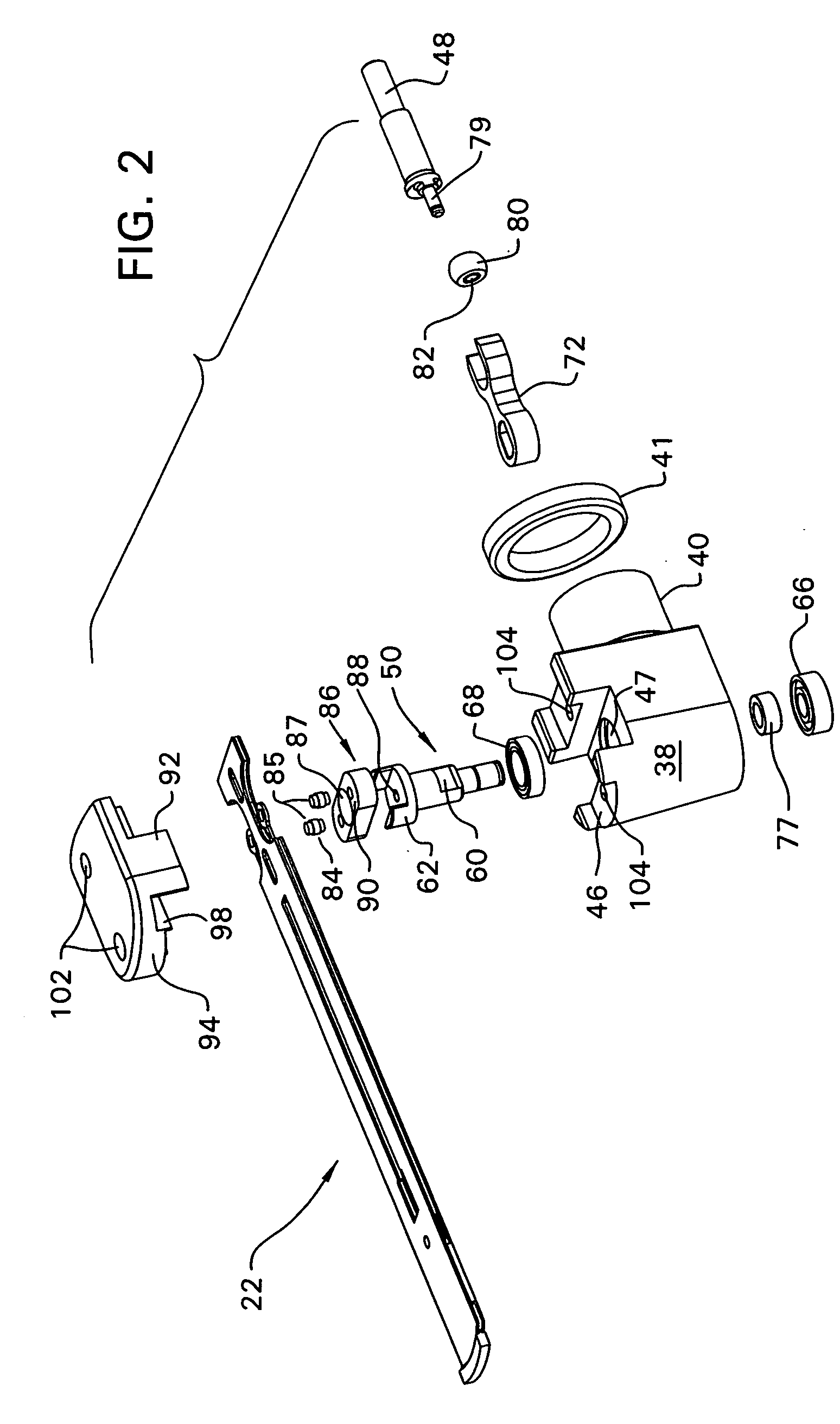
[0052] Located forward from the distally facing front face of the handpiece upper shell 28 is a head 38. Head 38 is the component of the saw 20 to which the blade ass...


PUM

PropertyMeasurementUnit
Thicknessaaaaaaaaaa
Forceaaaaaaaaaa
Widthaaaaaaaaaa

Abstract

A surgical sagittal saw including a handpiece from which a planar guide bar extends. A saw blade is mounted to the distal end of the guide bar to move across the guide bar. Drive rods connect the saw blade to a drive assembly in the handpiece, which drive assembly reciprocates the drive rods. The drive rods oscillate the saw blade across the distal end of the guide bar. The saw is used with a cutting guide that is in a fixed position relative to the bone or hard tissue to be cut. A capture element is disposed adjacent the guide surface and holds the guide bar to the guide surface so the cut is made along the desired cut plane.

Description

BACKGROUND OF THE INVENTION [0001] This invention is related generally to a surgical sagittal saw. More particularly, this invention is related to a surgical sagittal saw that minimally vibrates when used, does not excessively wear the cutting guide with which it is used and that has a complementary cutting guide that is relatively small in size. BACKGROUND OF THE INVENTION [0002] A sagittal saw is a powered surgical tool that is often used in an orthopedic surgical procedure. A sagittal saw generally includes a handpiece that houses a motor and the complementary control circuit that regulates the actuation of the motor. Extending forward, distally, from the handpiece, is a planar saw blade. The most forward end of the saw blade is formed with teeth for cutting hard tissue against which the blade is applied. A drive mechanism internal to the housing transfers the power developed by the motor to the blade. More particularly, the drive mechanism converts the rotary motion produced by ...

Claims


Application Information

Patent Timeline
IPC IPC(8): A61B17/14
CPCA61B17/14A61B17/141A61B17/157A61B2017/143B27B19/006A61B17/148A61B2017/145A61B17/149A61B17/144A61B17/142
Inventor CARUSILLO, STEVENPLASKON, GREGORY E.COLLAZO, CARLOS E.CANONACO, ALESSANDRO F.RUGO, ERICNEAL, DAVID J.
Owner STRYKER CORP
Why Eureka
Try Eureka