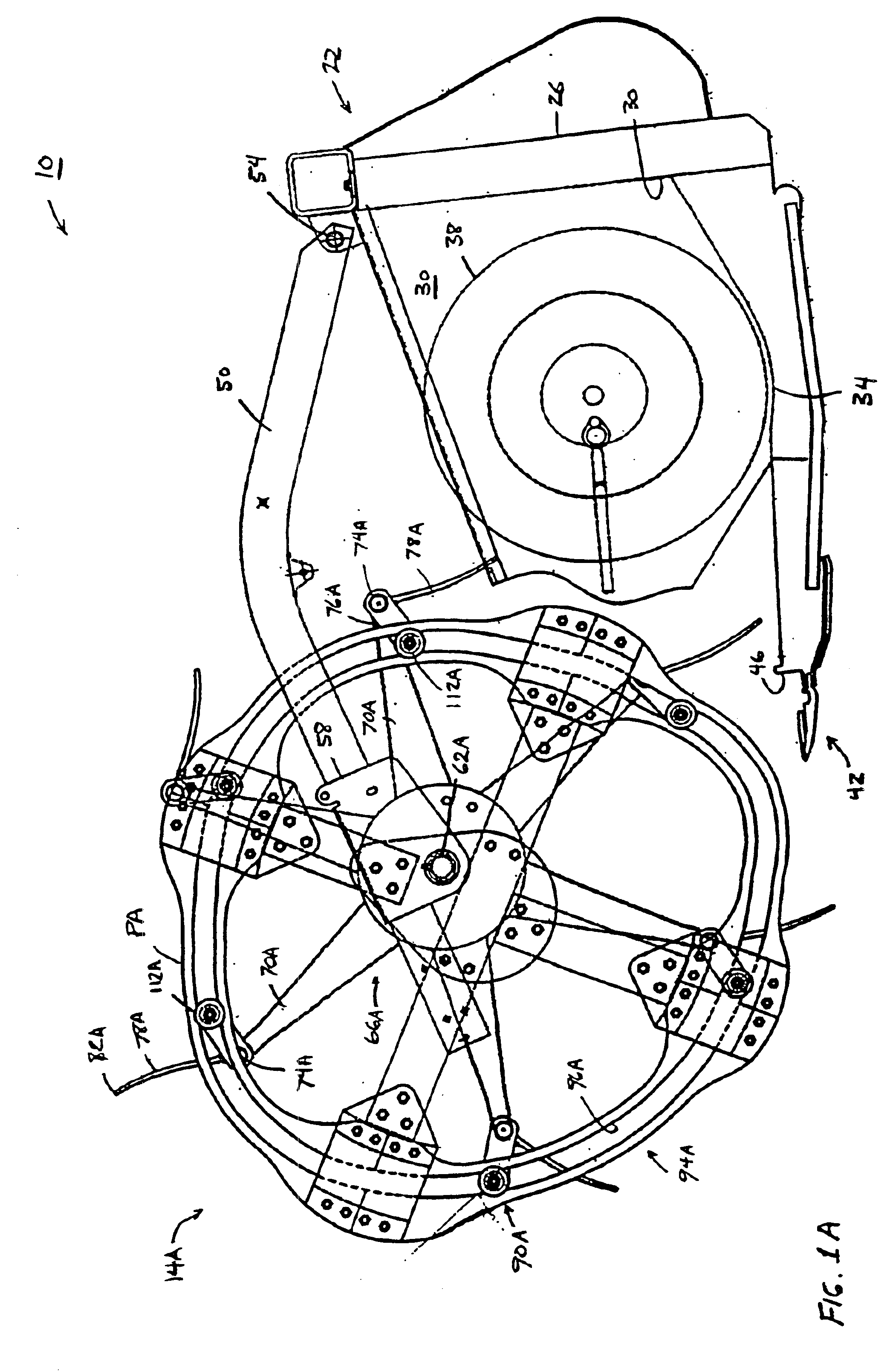
More particularly, the present invention provides a pickup reel for a harvester, the harvester including a harvesting platform including a frame having a
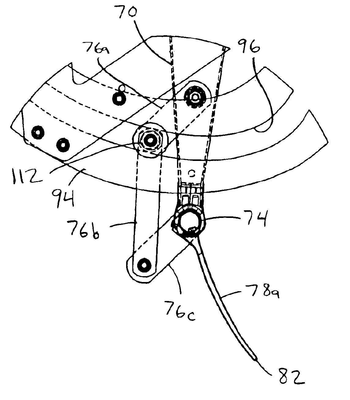
front edge and a cutter bar extending along the front edge. The pickup reel includes a reel support supported by the frame, a first shaft rotatably supported by the reel support and extending along an axis transverse to the frame, an arm extending radially from and being rotatable with the first shaft, a cam supported by the reel support and defining a generally endless cam path extending about the first shaft, the cam having a first axial side and a second axial side, a second shaft supported by the arm and being generally parallel to and radially spaced from the first shaft, the second shaft being rotatable relative to and rotatable with the arm, and a first
tine and a second tine supported by the second shaft for rotation with the second shaft, the first tine being located adjacent the first axial side of the cam, the second tine being located adjacent the second axial side of the cam, each of the tines having a tip, the tips being movable along a tip path during rotation of the first shaft, a cam follower engageable with the cam and movable along the cam path, and a
crank arm
assembly connected between the cam follower and the second shaft. Rotation of the first shaft and movement of the cam follower along the cam path cooperate to cause the tips to move along the tip path.
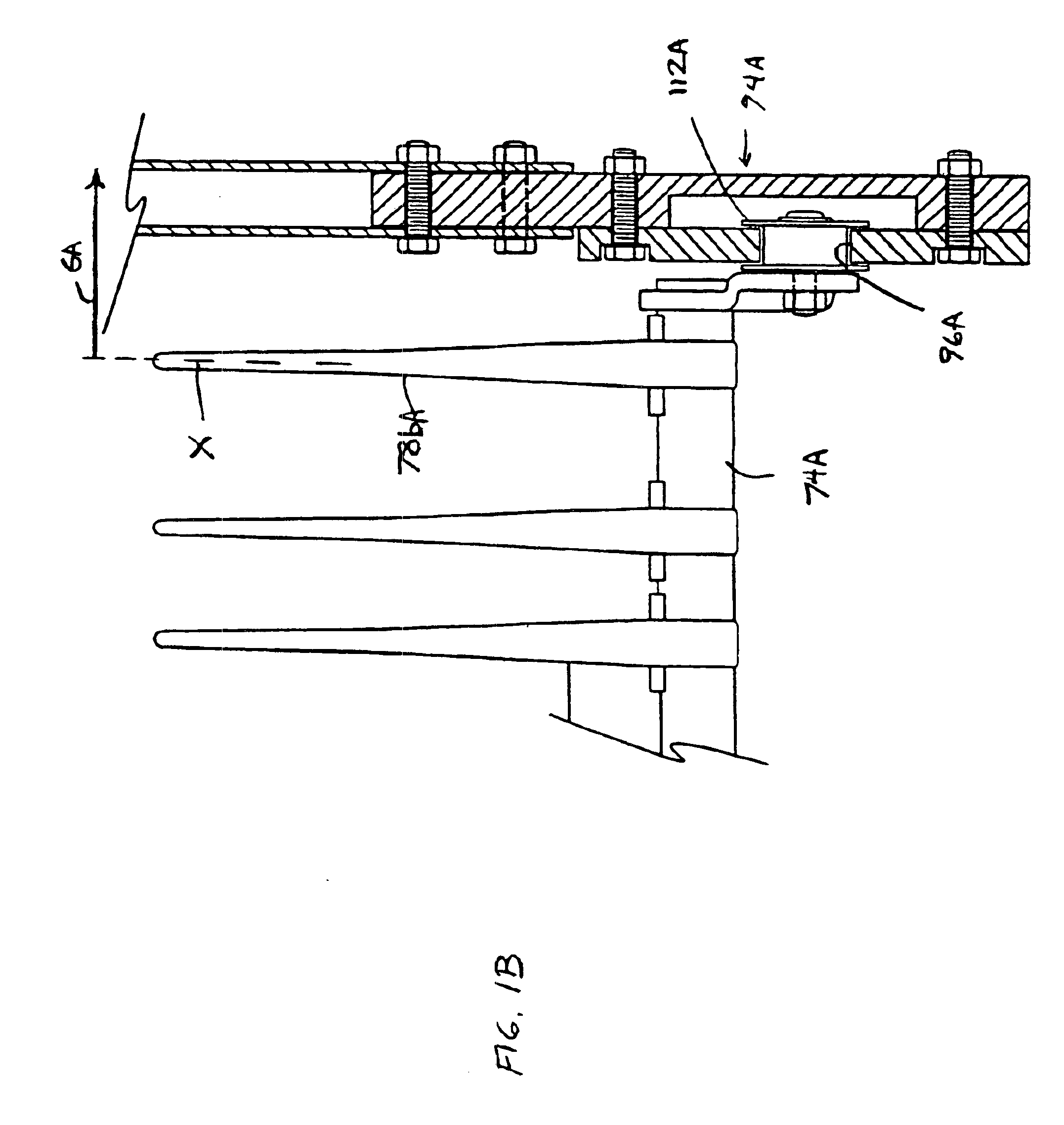
In addition, the present invention provides a pickup reel for a harvester, the harvester including a harvesting platform including a frame having a front edge and a cutter bar extending along the front edge. The pickup reel includes a reel support supported by the frame, a first shaft rotatably supported by the reel support and extending along an axis transverse to the frame, an arm extending radially from and being rotatable with the first shaft, a cam supported by the reel support and defining a generally endless cam path extending about the first shaft, the cam having a first axial side and a second axial side, a second shaft supported by the arm and being generally parallel to and radially spaced from the first shaft, the second shaft being rotatable relative to and rotatable with the arm, the second shaft extending from beyond the first axial side of the cam to beyond the second axial side of the cam, and a first tine and a second tine supported by the second shaft for rotation with the second shaft, the first tine being located adjacent the first axial side of the cam, the second tine being located adjacent the second axial side of the cam, each of the tines having a tip, the tips being movable along a tip path during rotation of the first shaft, a cam follower engageable with the cam and movable along the cam path, and a
crank arm
assembly connected between the cam follower and the second shaft. Rotation of the first shaft and movement of the cam follower along the cam path cooperate to cause the tips to move along the tip path.
Further, the present invention provides a pickup reel for a harvester, the harvester including a harvesting platform including a frame having a front edge and a cutter bar extending along the front edge. The pickup reel includes a reel support supported by the frame, a first shaft rotatably supported by the reel support and extending along an axis transverse to the frame, a cam supported by the reel support and defining a generally endless cam path and a perimeter extending about the first shaft, the cam having a first axial side and a second axial side, an arm extending radially from and being rotatable with the first shaft, the arm having an end and extending radially from the first shaft radially beyond the perimeter of the cam to the end, a second shaft supported by the arm
proximate the end and being generally parallel to and radially spaced from the first shaft, the second shaft being rotatable relative to and rotatable with the arm, the second shaft being rotatable with the arm along a shaft path, the shaft path being radially beyond the perimeter of the cam, and a first tine and a second tine supported by the second shaft for rotation with the second shaft, the first tine being located adjacent the first axial side of the cam, the second tine being located adjacent the second axial side of the cam, each of the tines having a tip, the tips being movable along a tip path during rotation of the first shaft, a cam follower engageable with the cam and movable along the cam path, and a
crank arm assembly connected between the cam follower and the second shaft. Rotation of the first shaft and movement of the cam follower along the cam path cooperate to cause the tips to move along the tip path.
In some aspects of the invention, at least one tine is located axially beyond the outer axial end of the cam. Accordingly, the axial gap between the axially-outermost inner tine and the cam and between the cam and the end sheet of the header is eliminated, and the tines sweep and lift
crop into the harvester across the entire width of the header.

