Embossing apparatus

Inactive Publication Date: 2005-01-25
THE PROCTER & GAMBLE COMPANY
View PDF43 Cites 122 Cited by
  • Summary
  • Abstract
  • Description
  • Claims
  • Application Information

AI Technical Summary

Benefits of technology

While the specification concludes with claims particularly pointing out and distinctly claiming the subject matter, which is regarded as the present invention, it is believed that the invention will be more fully understood from the following description taken in conjunction with the accompanying drawings, in which:
FIG. 1 is a simplified elevation view of one embodiment of a method of the present invention for producing a patt

Problems solved by technology

However, when the embossing patterns need be “unmatched,” (i.e., when the shape and dimensions of the protrusions of a first engraved roll are substantially not identical with that of the corresponding recessions of the second engraved roll, although the corresponding protrusions and recessions are still positioned in registry relative to each other such that they engage) the above described methods can become limited to situations wherein the unmatched parameters are relatively small.
The limitation is due to the limited thickness of the coating that can be applied to coat the elements of the embossing pattern without deforming the desired shape of the protrusions and recessions, for example, by rounding the sharp edges of the embossing elements and the like.
Unfortunately, the practicalities of laser burning limit the ability to separately burn the embossing patterns of a pair of rolls that would, when brought into engagement with each other, engage uniformly over a substantially entire area of the embossing patterns.
However, such problems often cannot be tolerated when “a substantial number” of uniform engagements is still not suf

Method used


Image

  • Embossing apparatus
  • Embossing apparatus
  • Embossing apparatus

Examples


example

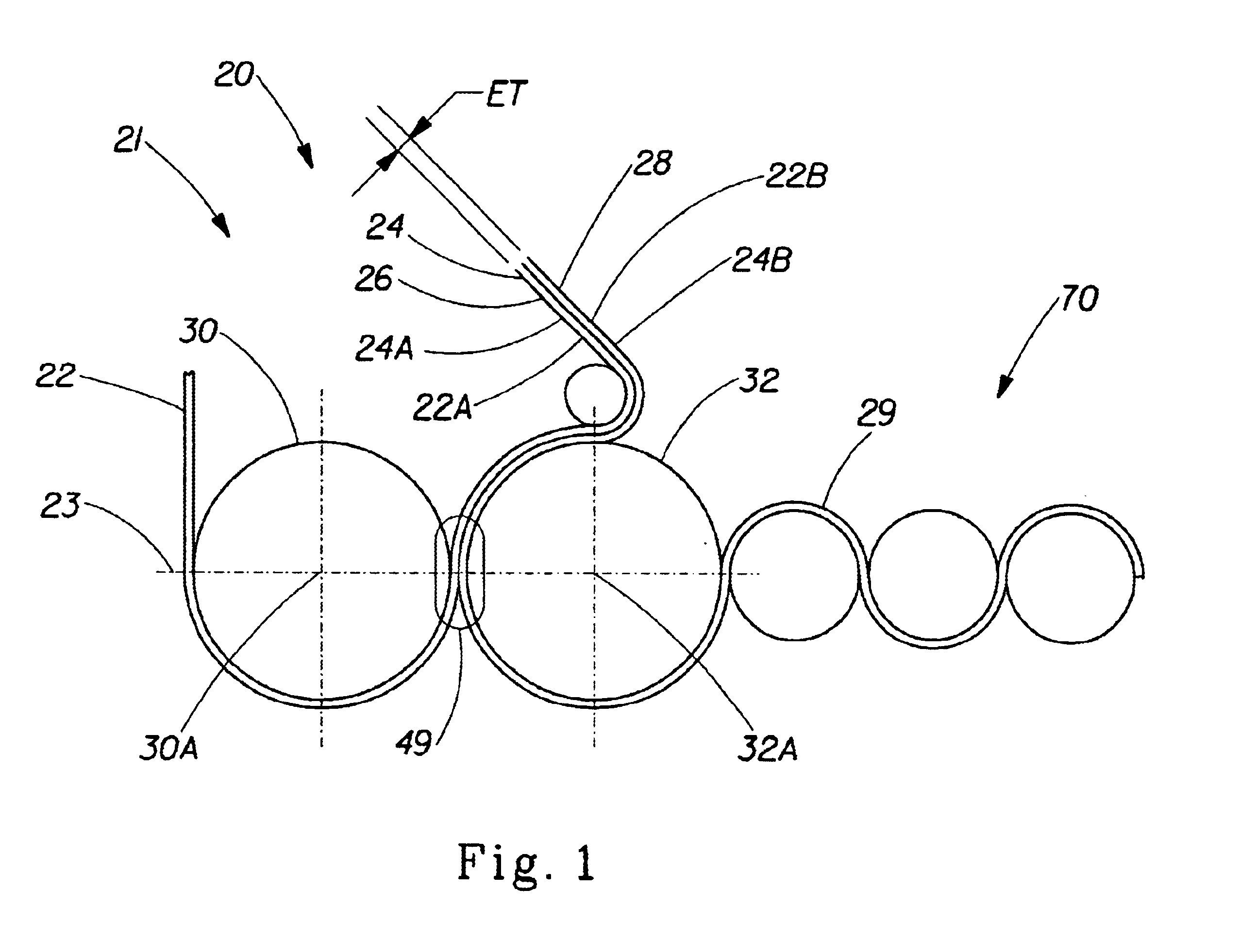
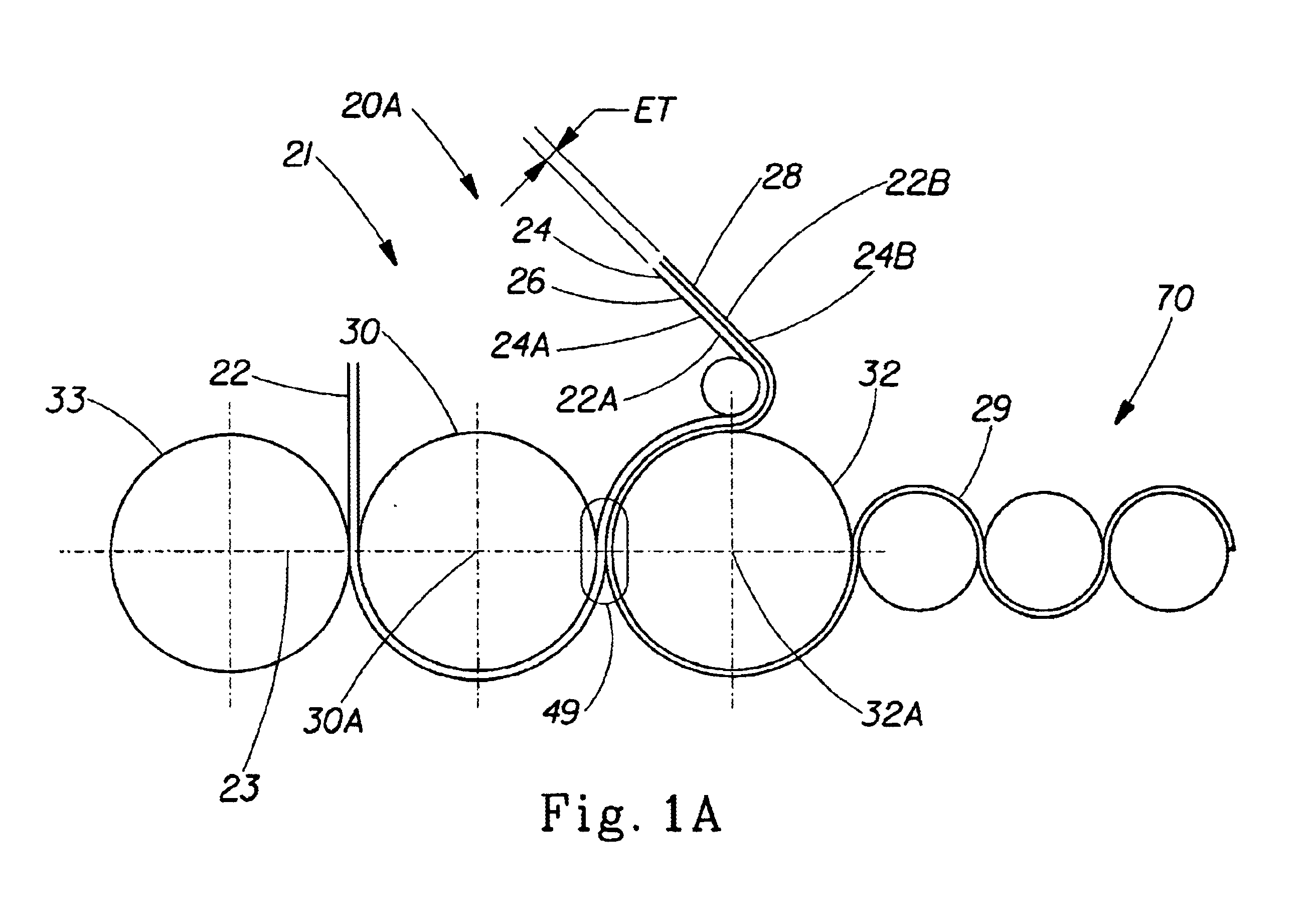
This example provides an exemplary method of providing one embodiment of the apparatus of the present invention for producing one embodiment of an embossed web material of the present invention such as a wrap material for wrapping a food product. The wrap material of the present invention must have preferably no pinholes or at least not more than about 12 pinholes per a material product size of about 72 square inches, in order to provide an effective protection of the wrapped food product.

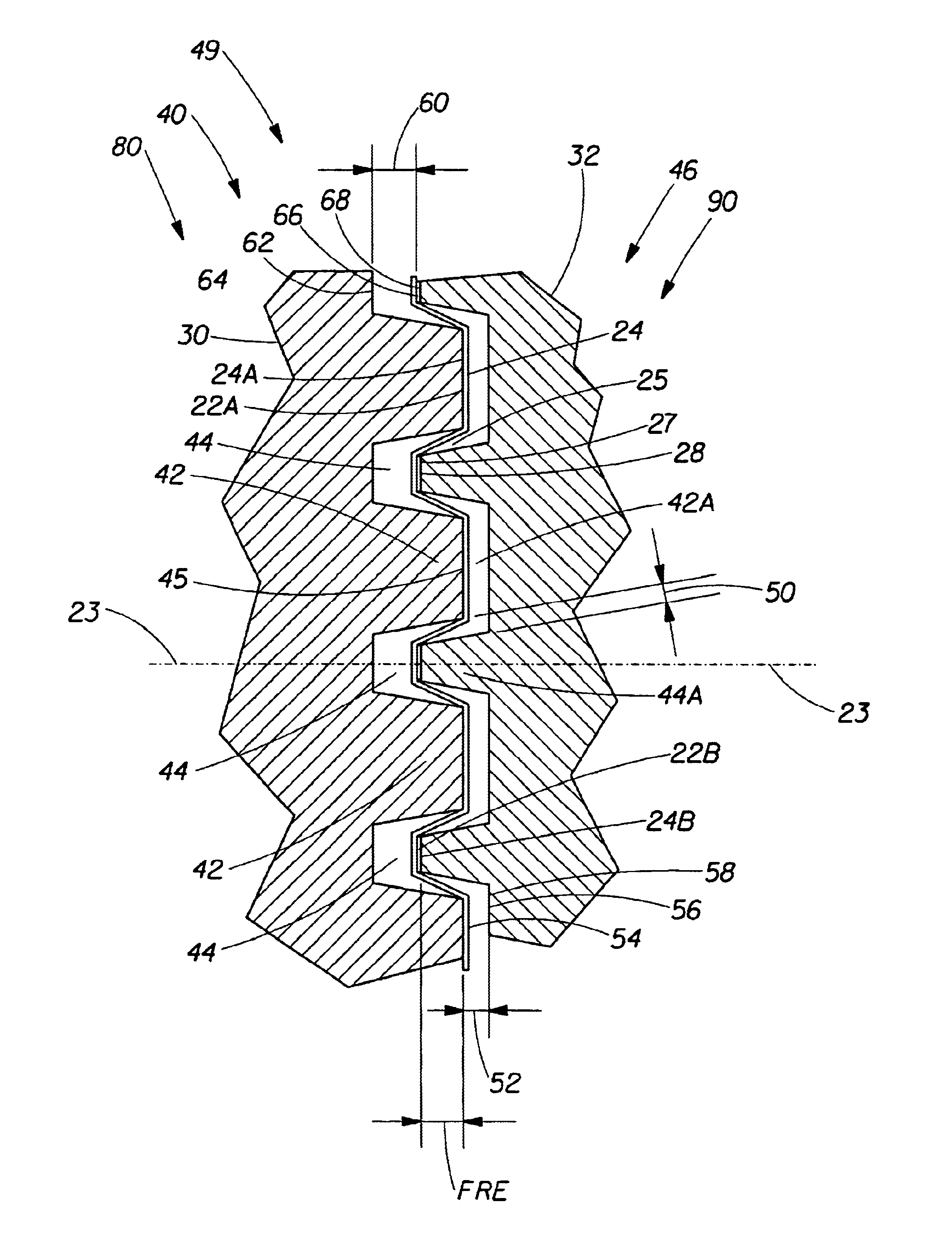
The wrap material of the present invention was formed from a relatively thin deformable film, and, thus can require a relatively small sidewall clearance—usually from about 0.002″ (about 0.050 mm) to about 0.008″ (about 0.203 mm)—between the unmatched embossing patterns of the embossing rolls forming the embossed web. However, it should be noted that the present example is intended to also represent other instances where the embossed material can be relatively thick, including films or, in particul...


PUM

PropertyMeasurementUnit
Lengthaaaaaaaaaa
Lengthaaaaaaaaaa
Fractionaaaaaaaaaa

Abstract

Disclosed is an embossing method and material made by the method, including at least a pair of embossing rolls having unmatched embossing patterns engraved independently from each other, and having enlarged sidewall clearances between adjacent, inter-engaged protrusions and recessions of the embossing patterns. The sidewall clearances can range from about 0.002″ (about 0.050 mm) to about 0.050″ (about 1.27 mm). The width of the protrusions can be greater than about 0.002″ or about 0.050 mm. The peripheral surface of at least one of the embossing rolls can comprise a metal, a plastic, a ceramic, or a rubber. Also disclosed is an embossed web material capable of being used as a wrap material for food products, made by the above process.

Description

FIELD OF THE INVENTIONThe present invention relates to embossing methods and materials. Particularly, to embossing methods and materials produced by at least a pair of inter-engaged embossing rolls having unmatched embossing patterns separated from each other by a substantially large sidewall clearance.BACKGROUND OF THE INVENTIONMany embossed web or sheet-type materials can be fabricated by a pair of embossing rolls, wherein each roll has an embossing pattern engraved on the peripheral surface of the roll. The rolls are inter-engaged with each other via their respective embossing patterns at a certain radial depth of engagement. The inter-engaged rolls rotate in opposite directions and impart embossing patterns on both sides of a deformable web or sheet-type material passing between the rotating embossing rolls. The web or sheet-type material becomes deflected and deformed at the points of contact with protrusions of the inter-engaged embossing patterns of the rolls, pushing the web...

Claims


Application Information

Patent Timeline
IPC IPC(8): B31F1/00B31F1/07
CPCB31F1/07B31F2201/072B31F2201/0728B31F2201/0733Y10T428/24479B31F2201/0748B31F2201/0779B31F2201/0787B31F2201/0738
Inventor VAUGHN, JEFFREY MOSSMCNEIL, KEVIN B.
Owner THE PROCTER & GAMBLE COMPANY
Why Eureka
Try Eureka