
Planar byte memory organization with linear access

a memory organization and linear access technology, applied in the field of planar byte memory organization, can solve the problem of a number of places being liable for costs

Inactive Publication Date: 2005-01-25
XUESHAN TECH INC
View PDF2 Cites 122 Cited by
  • Summary
  • Abstract
  • Description
  • Claims
  • Application Information

AI Technical Summary

Benefits of technology

This approach enhances memory access efficiency by minimizing bandwidth waste and optimizing performance for both graphics and video applications, allowing for flexible mode operation to suit different application needs.

Problems solved by technology

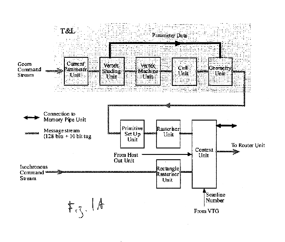
Some observations contrasting this architecture to earlier ones of 3Dlabs:The message stream does not visit every unit.Trying to route a linear message stream though the texture pipes is fairly problematic, although fanning it out like in Gamma 3 would have been an option.It turns out that the texture units in the texture pipe have little or no state or any need for the color and coordinate information, but are heavily pipelined or have deep latency FIFOs.
If the message stream were increased in width to give the required bandwidth then the cost would be borne in a number of places.

Method used


Image

  • Planar byte memory organization with linear access
  • Planar byte memory organization with linear access
  • Planar byte memory organization with linear access

Examples


Embodiment Construction

The numerous innovative teachings of the present application will be described with particular reference to the presently preferred embodiment (by way of example, and not of limitation).

The present application discloses an improvement on a graphics memory architecture which is oriented in a tiled format. (In the preferred system example, memory is organized as 8 byte by 8 byte tiles that are stacked through memory; and data is accessed by tile number instead of by byte position.)

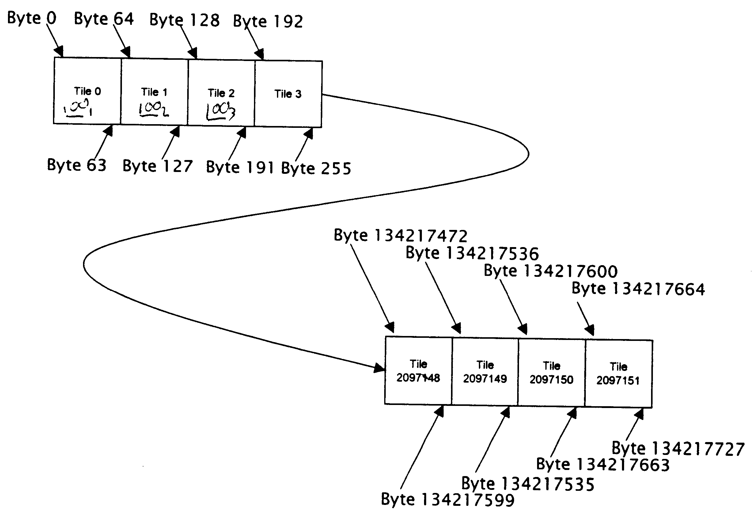
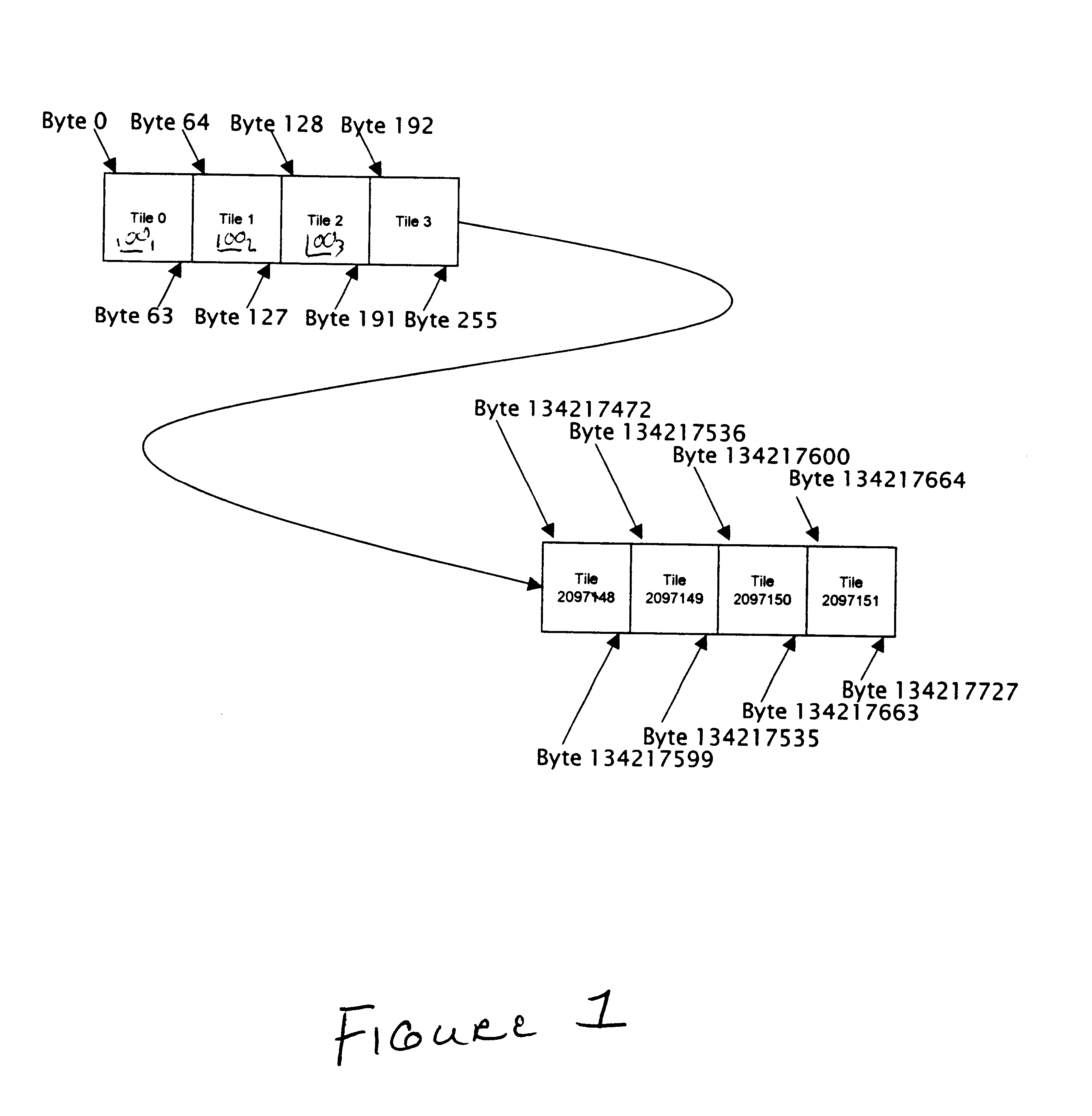
FIG. 1 shows how the memory system is preferably organized as 8 byte by 8 byte tiles 100 that are stacked through memory. Instead of addressing by byte position, data is accessed by tile number.

Normally, each tile corresponds to a region of a buffer (perhaps the framebuffer or a texture). If the data type held in the buffer needs more than one byte per entry, the bytes are preferably held in separate tiles. (Thus this organization may be described as a “byte planar” format. FIG. 2 shows a 1024×768 screen at ...


PUM


Abstract

A graphics memory architecture in which row addresses are permuted, in a basically tile-oriented storage architecture, so that fast parallel access is provided both by scanlines (for video operations) and also by tiles (for graphics operations).

Description

BACKGROUND AND SUMMARY OF THE INVENTIONThe present invention relates to graphics memory architectures, and particularly to architectures optimized for both video-driven and 3D-graphics-driven performance.A standard graphics memory organization stores data for a scanline at sequential addresses. This is convenient for the display of data, which has to be accessed in scanline order, but is inefficient for drawing operations.The performance of drawing often depends on maintaining locality of data. This may be due to caches or to the row / column organization of dynamic memories. Drawing operations rarely stay on the same scanline for long and generally move in Y as well as X. Organizing memory for efficient access only in the X dimension degrades overall performance.Planar Byte Memory Organization with Linear AccessThe present application discloses an improvement on a graphics memory architecture which is oriented in a tiled format. (In the preferred system example, memory is organized a...

Claims


Application Information

Patent Timeline
Patent Type & Authority Patents(United States)
IPC IPC(8): G09G5/39G09G5/36
CPCG09G5/39G09G2360/122G09G2360/121
Inventor BALDWIN, DAVID ROBERTMURPHY, NICHOLAS J. N.
Owner XUESHAN TECH INC
Learn More