Alignment and correction template for optical profilometric measurement

a technology of alignment and correction template, applied in the field of surface profiling and apparatus, to achieve the effect of faster and more efficient testing capability

Inactive Publication Date: 2005-01-25
BRUKER NANO INC
View PDF2 Cites 8 Cited by
  • Summary
  • Abstract
  • Description
  • Claims
  • Application Information

AI Technical Summary

Benefits of technology

It is therefore an objective of this invention to provide an automatic procedure for identifying regions of interest in a test sample, so that profilometric testing can be limited to such regions to provide a faster and more efficient testing capability.

Problems solved by technology

In turn, the template patterns also become aligned with the regions of interest in the test part and interferometric analysis can be limited to data corresponding to the pixels contained within those patterns.

Method used


Image

  • Alignment and correction template for optical profilometric measurement
  • Alignment and correction template for optical profilometric measurement
  • Alignment and correction template for optical profilometric measurement

Examples


Embodiment Construction

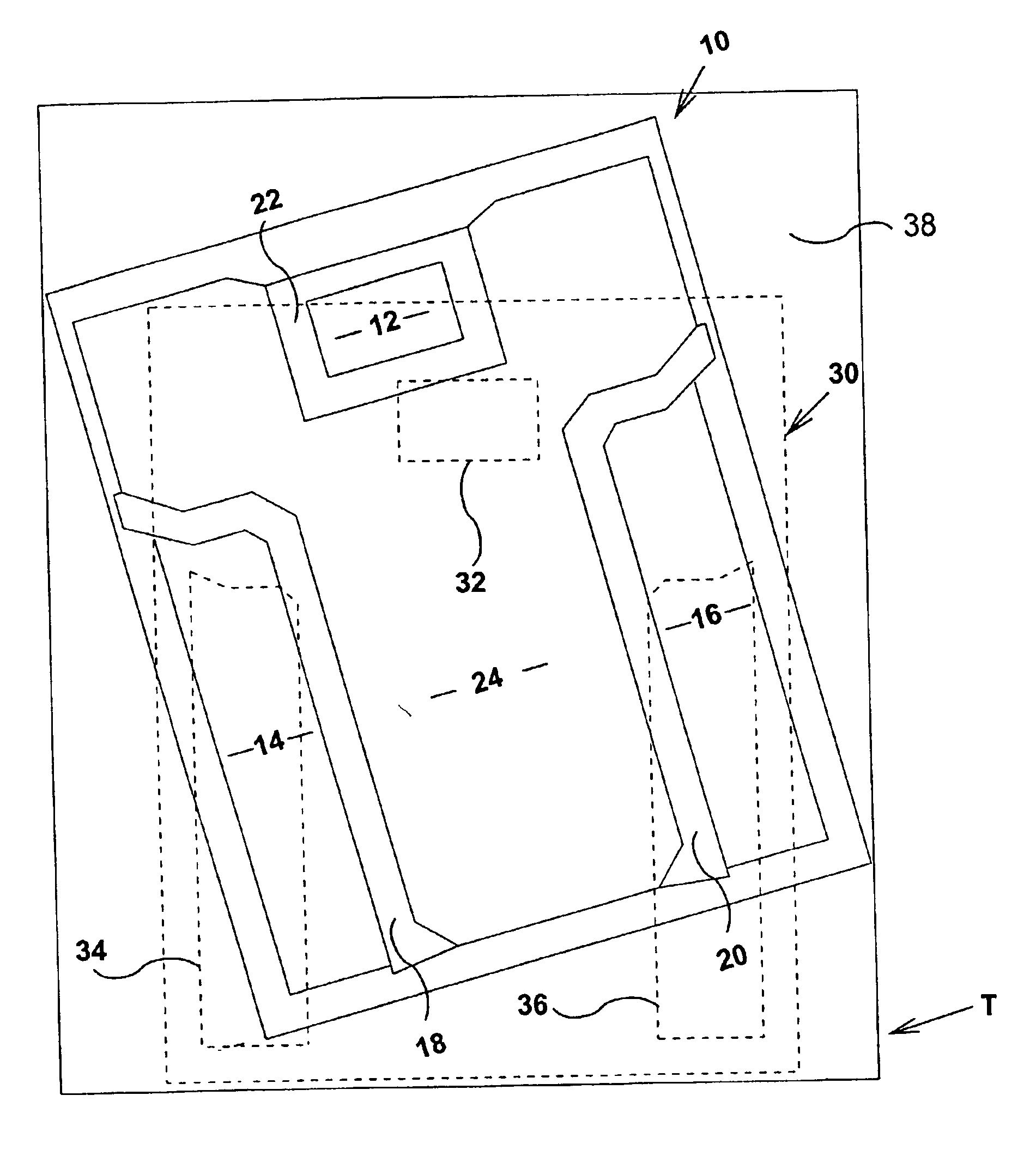
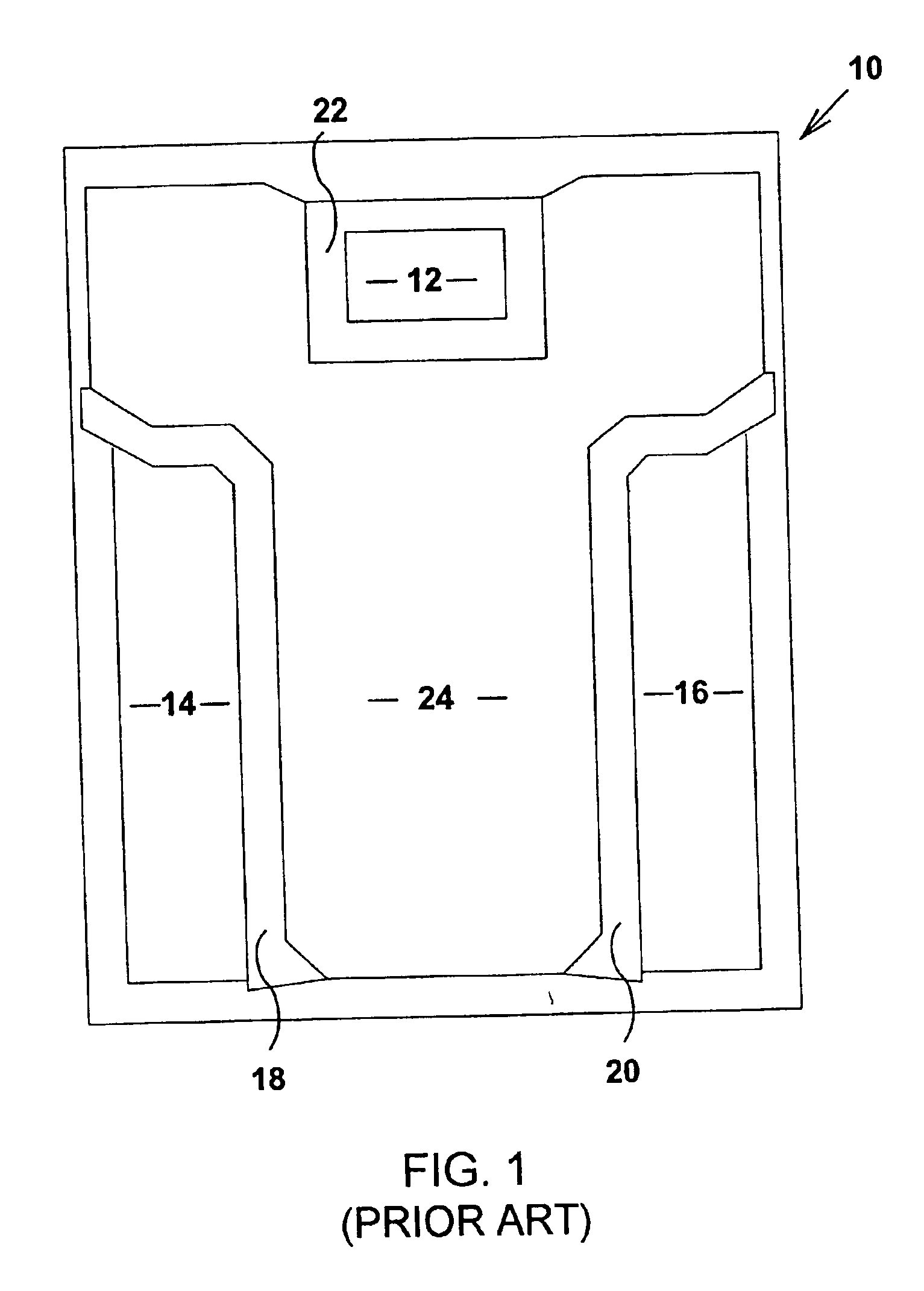
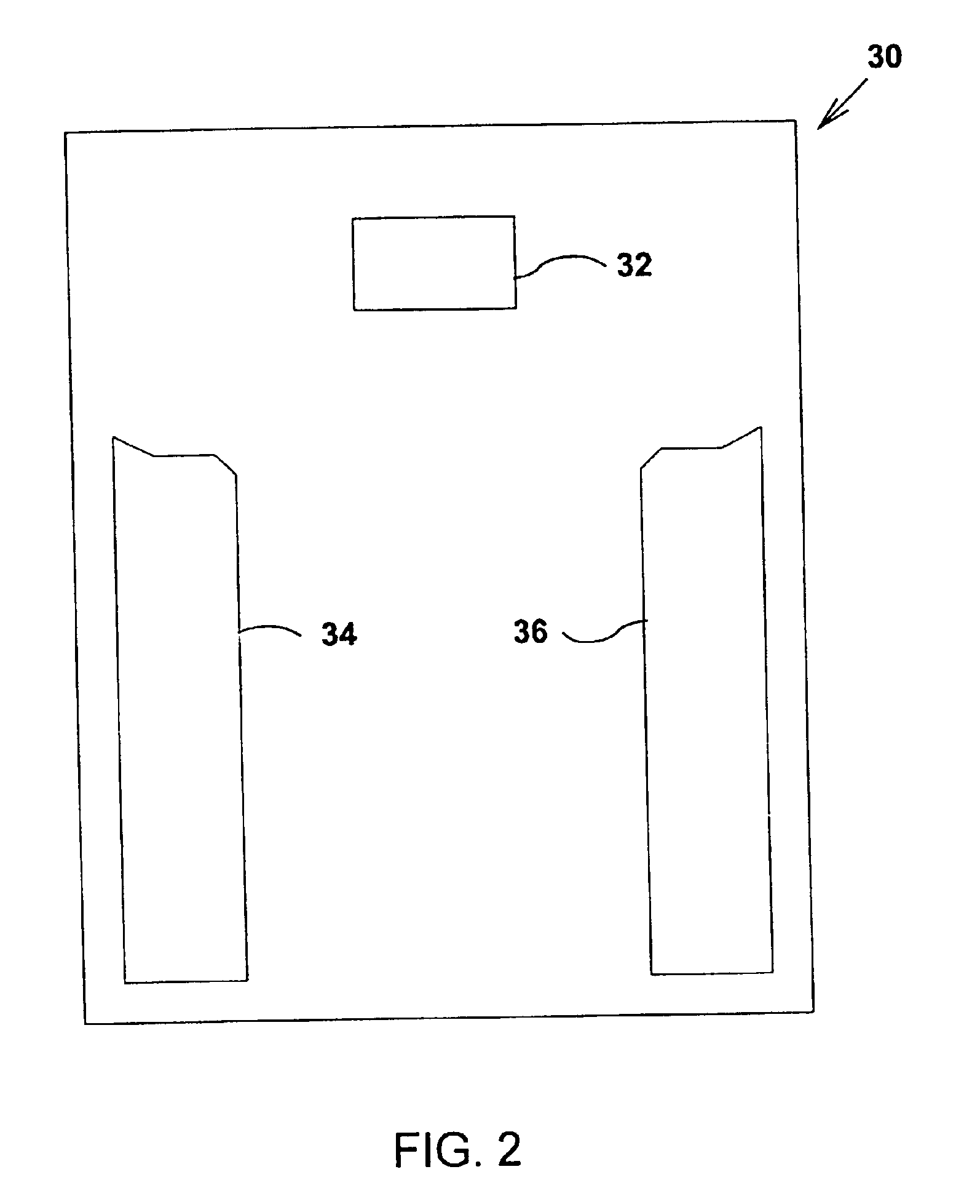
This invention is based on the realization that the approach disclosed in U.S. Ser. No. 09 / 585,370 may be generalized for use with any profilometric technique so long as the sample surface being profiled contains distinct regions separated by identifiable boundaries. These boundaries and / or other features of the islands defined thereby can be used to find a match between a given landmark region in the sample surface a corresponding predetermined landmark pattern in the template. This match is then used to align the template with the sample surface so that the selected patterns in the template overlay the regions of interest in the sample surface.

Phase-shifting interferometry (PSI) is used herein to describe the invention by way of example, but those skilled in the art would readily recognize that the same concepts are also applicable to other profilometric techniques. For example, a boundary between regions may be found in equivalent fashion using modulation data in phase-shifting i...


PUM

PropertyMeasurementUnit
optical interferometryaaaaaaaaaa
phase shifting interferometryaaaaaaaaaa
confocal microscopyaaaaaaaaaa

Abstract

An electronic template delineating distinct selected patterns corresponding to predetermined regions of interest in a sample part is used to limit analysis to those regions. The surface of the sample is first measured using conventional techniques. The data so acquired are used to identify boundaries between distinct regions, which are then compared to a predetermined pattern boundary in the template to find a best-fit match. The position of the pattern is then shifted to overlay the match, thereby automatically aligning the template's selected patterns with the regions of interest in the sample surface. As a result, profilometric analysis can be limited to the regions of interest. Correction factors are also assigned to each selected pattern in the template to account for physical differences in the corresponding regions of interest of the sample part that affect the profilometric measurement.

Description

BACKGROUND OF THE INVENTION1. Field of the InventionThis invention pertains to the general field of surface profiling and apparatus for aligning a sample surface to a template that defines regions of special interest. In particular, the invention provides a novel approach for matching the regions of interest in a test part to a corresponding template in order to effect the alignment of the part, and further utilizes the template for correcting measurement errors resulting from material and wavelength variations between adjacent regions in the part.2. Description of the Prior ArtParts that are measured by surface profilometry for quality control often contain distinct regions separated by a boundary delineating different properties, such as materially different heights, for example. The surface characteristics of some of these regions may be critical to the performance of the part, while others may be totally irrelevant. Therefore, it is typically preferable to measure only the regio...

Claims


Application Information

Patent Timeline
Patent Type & Authority Patents(United States)
IPC IPC(8): G11B5/60G11B5/187G11B5/455
CPCG11B5/1871G11B5/6005G11B5/455
Inventor FARRELL, COLIN T.MARTINEZ, ANTHONY L.SCHMIT, JOANNAKRELL, MICHAEL B.
Owner BRUKER NANO INC
Why Eureka
Try Eureka