Press brake tool and tool holder

a technology of press brakes and tool holders, which is applied in the direction of manufacturing tools, shaping tools, metal-working apparatus, etc., can solve the problems of difficult horizontal sliding of the forming tool horizontally from the holder, and the difficulty of replacing the forming tool mounted to the upper table of the press brakes

Active Publication Date: 2005-02-01
WILSON TOOL INT
View PDF12 Cites 33 Cited by
  • Summary
  • Abstract
  • Description
  • Claims
  • Application Information

AI Technical Summary

Problems solved by technology

The forming tools that are mounted to the upper table of a press brake often are not so easily replaced, however.
If a forming tool of some length (and hence of some substantial weight) is to be replaced, it sometimes is difficult to slide the forming tool horizontally from its holder because of the proximity of neighboring forming tools which may themselves have to be removed in order to complete the tool exchange process.

Method used


Image

  • Press brake tool and tool holder
  • Press brake tool and tool holder
  • Press brake tool and tool holder

Examples


Embodiment Construction

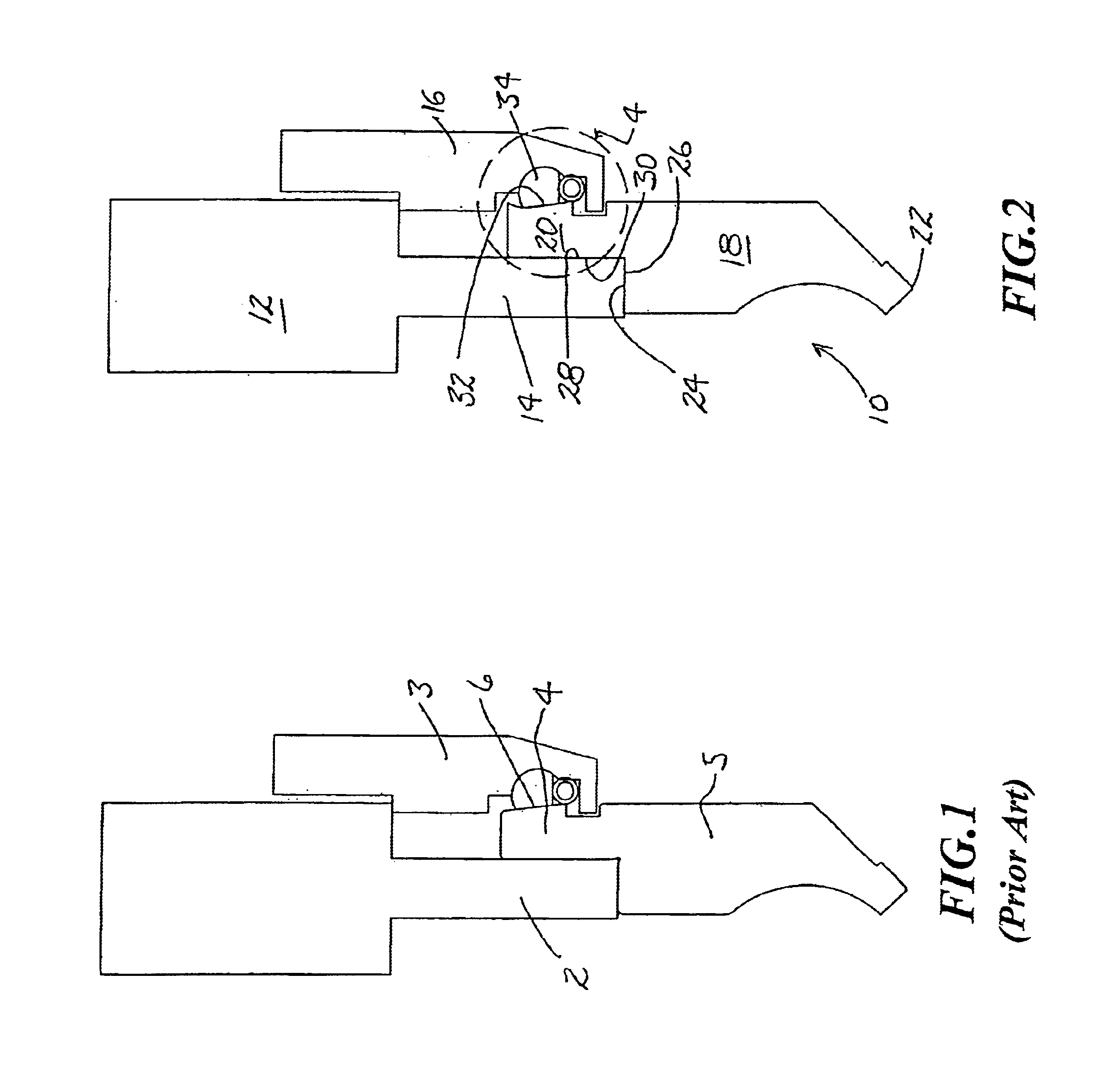
As background, FIG. 1 shows an Amada-style tool and tool holder, the tool holder having a vertical mounting plate 2 and a clamp 3. The tang 4 of a press brake tool 5 has a slanted surface 6 so configured that when the tool is forced upwardly between the plate and the clamp, the clamp is cammed open by the slanted surface 6. The holder is generally of the type shown in U.S. Pat. No. 5,619,885, assigned on its face to Amada Metrecs Company, Ltd.

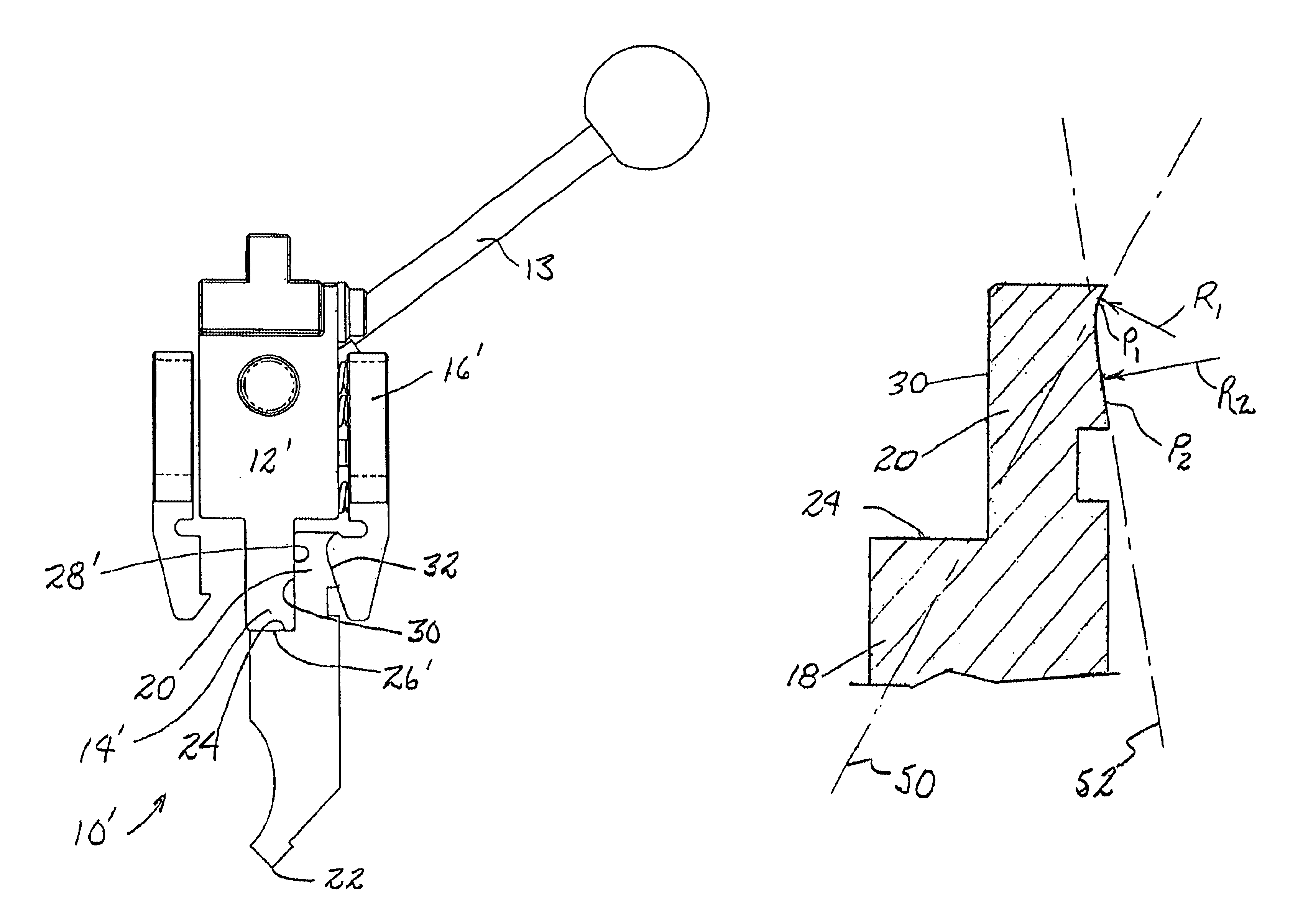
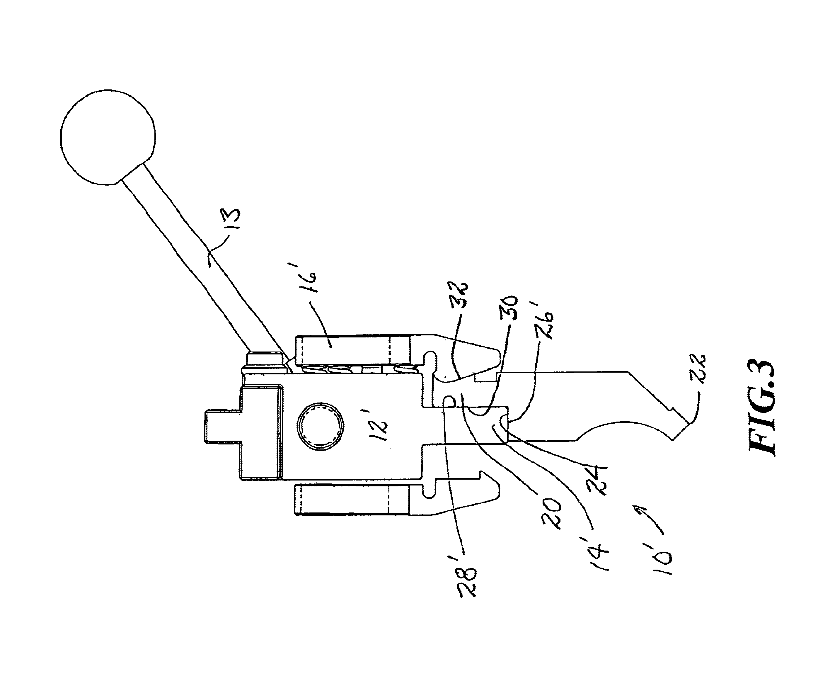
Referring now to FIG. 2, a similar press brake tool holder is shown having a body 12, a downwardly extending plate 14 and a clamp 16. It will be understood that in certain of these schematic views of well known press brake tool holders, the structure holding the clamp 16 to the remainder of the holder has been omitted. It should be understood that the omitted structure is such that the clamp 16 generally pivots about its connection to the holder 12 such that the lower portion of the clamp is moved generally horizontally toward and away from the...


PUM

PropertyMeasurementUnit
radius R2aaaaaaaaaa
radius R2aaaaaaaaaa
radius R1aaaaaaaaaa

Abstract

A press brake tool and tool holder. The tool is provided having a body that terminates downwardly in a work piece engaging surface and that includes a tang extending upwardly from the body for reception in a tool holder. The tang has a first wall defining a vertical surface for engagement with a cooperating vertical surface of a tool holder, and a second wall on the reverse side of the tang that defines an arcuate, concave surface engagable with a clamp of the tool holder. The concave surface includes an upper contact surface tangent to a plane that is downwardly convergent with respect to the vertical surface such that a force delivered to the contact surface includes an upward component tending to lift the tang into the tool holder. The upper contact surface may be formed on a first radius about a horizontal axis and is tangent to a first plane that is downwardly convergent with respect to said vertical surface. The concave surface may include a lower contact surface formed on a second, larger radius about a horizontal axis and that is tangent to a second plane that is upwardly convergent with respect to said vertical surface, the angle between the vertical and said first plane being greater than the angle between the vertical and the second plane so that the clamp delivers a net upwardly force to the tool.

Description

FIELD OF THE INVENTIONThis invention relates to press brake technology, and particularly to tools and tool holders used in various press brakes.BACKGROUND OF THE INVENTIONPress brakes are employed to bend metal sheets into desired configurations. A press brake commonly is equipped with a lower table and an upper table, one or both of which are moveable to close the tables upon a workpiece positioned between the tables. Forming tools are mounted to the tables so that when the tables are brought together, a work piece between the forming tables is bent into an appropriate shape. The upper table commonly includes a male forming tool having a lower work piece-deforming portion of a desired shape, such as a right angled bend, and the lower table commonly has an appropriately shaped and aligned die, which for example may be V-shaped and open upwardly to receive the work piece-deforming portion of the upper tool. A metal sheet positioned between the tool and die thus is pressed into a desi...

Claims


Application Information

Patent Timeline
Patent Type & Authority Patents(United States)
IPC IPC(8): B21D5/02
CPCB21D5/0209
Inventor JOHNSON, PAUL T.ROGERS, BRYAN L.
Owner WILSON TOOL INT
Why Eureka
Try Eureka