Quick release fastener for flags and flag staffs

Inactive Publication Date: 2005-02-01
SHIELDS ROBERT
View PDF9 Cites 8 Cited by
  • Summary
  • Abstract
  • Description
  • Claims
  • Application Information

AI Technical Summary

Benefits of technology

The present invention comprises an apparatus for quickly and easil

Problems solved by technology

This periodic relocation facilitates even wear of the grasses of the gr

Method used


Image

  • Quick release fastener for flags and flag staffs
  • Quick release fastener for flags and flag staffs
  • Quick release fastener for flags and flag staffs

Examples


Example

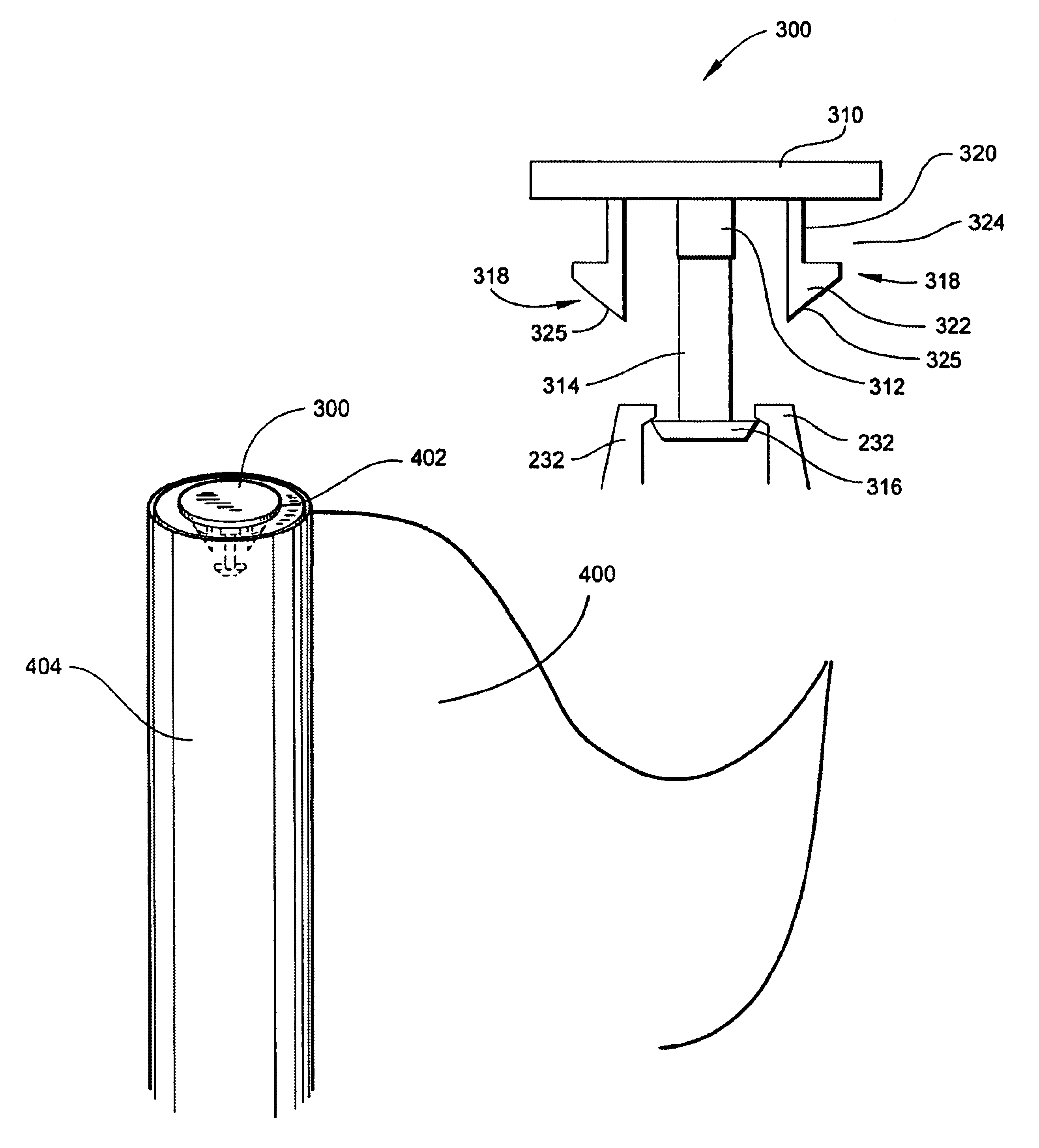
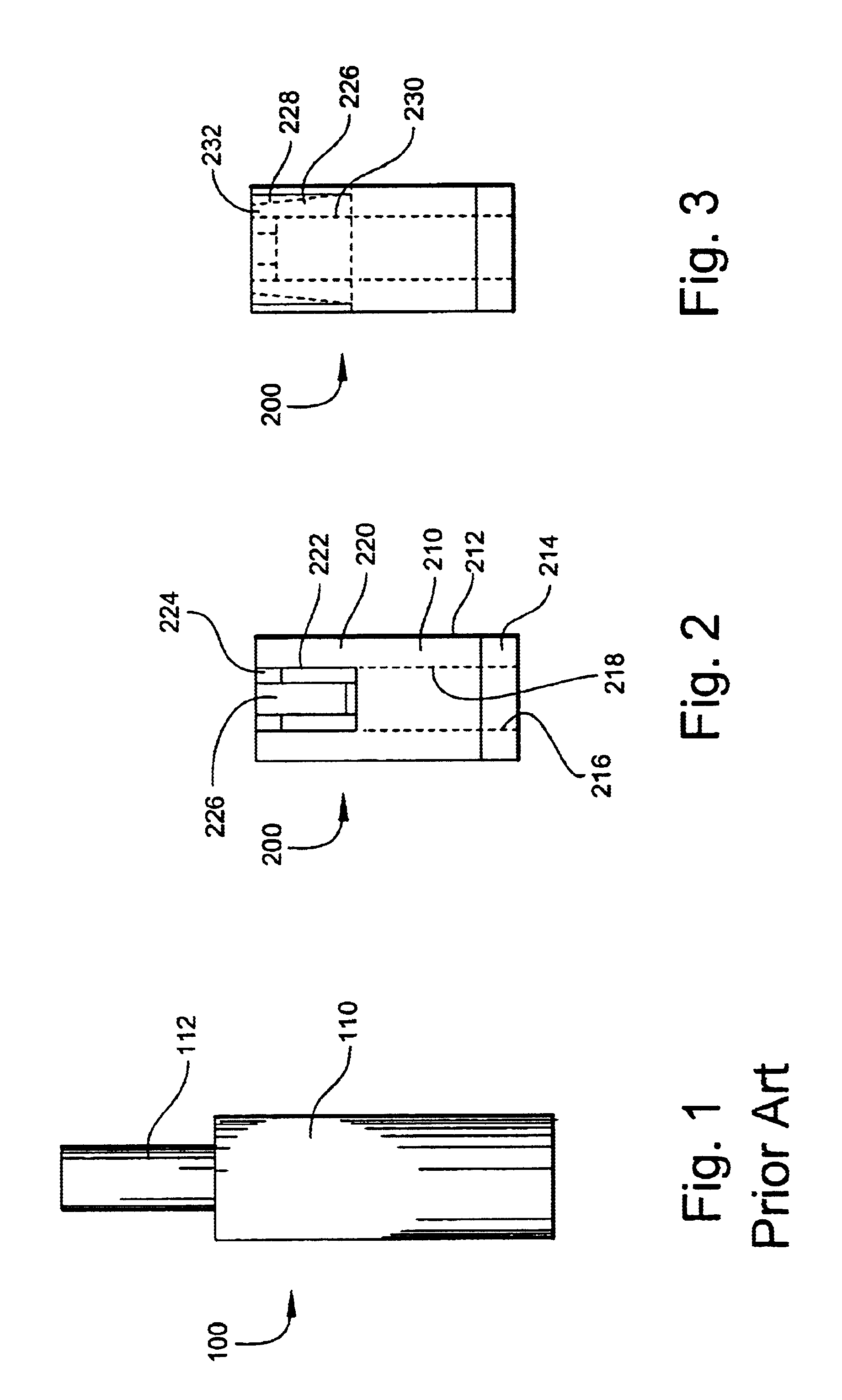
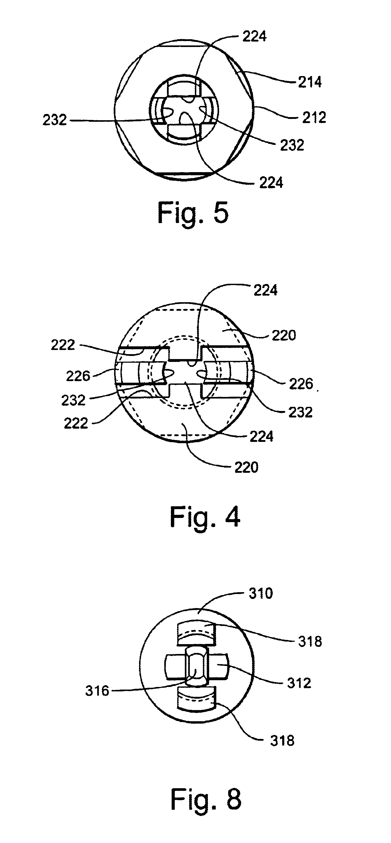
The quick release fastener of the present invention is composed of two basic elements, a flag staff attachment 200, as depicted in FIGS. 2 thru 5, and a retaining cap 300, as depicted in FIGS. 6 thru 8, which are used in conjunction with a standard flag staff 100, FIG. 1.

Referring first to FIG. 1, while not deemed to be a part of the present invention, a typical flag staff 100 consists of a shaft 110 topped by a threaded rod 112. A sleeve (not shown) formed in a flag (not shown) is typically slipped over shaft 110 such that threaded rod 112 extends through an aperture (not shown) in the top of the sleeve (not shown) and then secured with a nut (not shown). The instant invention is adapted to utilize the basic structure of flag staff 100, as will be described hereinbelow.

Referring now to FIGS. 2 thru 5, flag staff attachment 200 has a body 210 having a substantially cylindrical exterior 212 having a diameter substantially equal to that of a typical flag staff 100, and a substantially...


PUM


Abstract

An apparatus for quickly installing a flag on and removing a flag from a golf hole flag staff is disclosed. A flag staff attachment having laterally displaceable retaining clips is threaded onto the top of a golf hole flag staff, and a retainer cap is installed through the aperture at the top of the sleeve of a golf hole flag. Laterally displaceable retaining clips on the retaining cap engage the flag sleeve's aperture, thereby securing the retaining cap to the flag. An engagement member on the retaining cap displaces the retaining clips of the flag staff attachment, thereby allowing the engagement member to pass therebetween, thereby securing the flag to the staff.

Description

BACKGROUND OF THE INVENTION1. Field of the InventionThe present invention relates to sporting equipment, especially as it relates to the game of golf. More particularly, the invention comprises a system for quickly and easily changing the flag attached to a staff used for indicating a golf green hole.2. Description of the Prior ArtIn the game of golf, the hole, or cup, is typically relocated to various spots around the green on a regular basis. This periodic relocation facilitates even wear of the grasses of the green and increases the challenge of the course by moving the target hole. A staff topped with a flag is placed in the hole so that a golfer may determine the location of the hole from the tee or the fairway, up to several hundred yards away. The flags are coded, usually by color, to indicate whether the hole is toward the front, center or rear of the green, thereby aiding the golfer in selecting the club to use for the distance to the hole. Therefor, it is desirable to be a...

Claims


Application Information

Patent Timeline
IPC IPC(8): G09F17/00
CPCG09F17/00Y10T403/7005Y10T403/606
Inventor SHIELDS, ROBERT
Owner SHIELDS ROBERT
Why Eureka
Try Eureka