Cross-connector for interfacing multiple communication devices

Inactive Publication Date: 2005-02-01
CHIMIAK WILLIAM J
View PDF19 Cites 20 Cited by
  • Summary
  • Abstract
  • Description
  • Claims
  • Application Information

AI Technical Summary

Benefits of technology

A further object of the invention is to increase the efficient use of space associated with installing and testing networks by eliminating the use of bulky palm hubs and lengthy cross-connector cables.
Yet another object of the invention is to reduce the costs associated with installing and testing networks by eliminating the necessity for network engineers to purchase device-specific cross-connector devices.

Problems solved by technology

Unfortunately, a single shared cable limits the size of the Ethernet network.
In certain situations, however, the standard RJ45 connector limits the number of devices that a network engineer can incorporate into a particular network.
For example, if a network configuration or a troubleshooting technique requires that a personal computer (PC) connect to another PC, and a cross-connection is not provided, then the connection is not possible due to incompatible signal paths.
Likewise, if a network configuration or troubleshooting technique requires that a hub connect to another hub, or that a hub connect to a router, and a cross-connection is not provided, then the network engineer is unable to configure the network structure or to properly evaluate an inoperable communication device (e.g., hub).
Further, if an uplink port of a hub incorporates an older BNC (British Naval Connector or Bayonet Nut Connector) connector, the hub is unusable.
In these situations, the options available to the network engineer seeking to interconnect multiple devices are somewhat limited.
First, the network engineer may purchase or construct a cumbersome Ethernet crossover cable.
This option is costly, labor intensive, and utilizes valuable space when working in close quarters (i.e., small areas behind local servers and shelves supporting telecommunication links).
Both options (i.e., cross-over cables or palm-size hubs) take up valuable space in an engineer's laptop case or network monitor case.

Method used


Image

  • Cross-connector for interfacing multiple communication devices
  • Cross-connector for interfacing multiple communication devices
  • Cross-connector for interfacing multiple communication devices

Examples


Embodiment Construction

The present invention will now be described more fully hereinafter with reference to the accompanying drawings, in which a preferred embodiment of the invention is shown. This invention may, however, be embodied in many different forms and should not be construed as limited to the embodiments set forth herein. Rather, these embodiments are provided so that this disclosure will be thorough and complete, and will fully convey the scope of the invention to those skilled in the art. Like numbers refer to like elements throughout.

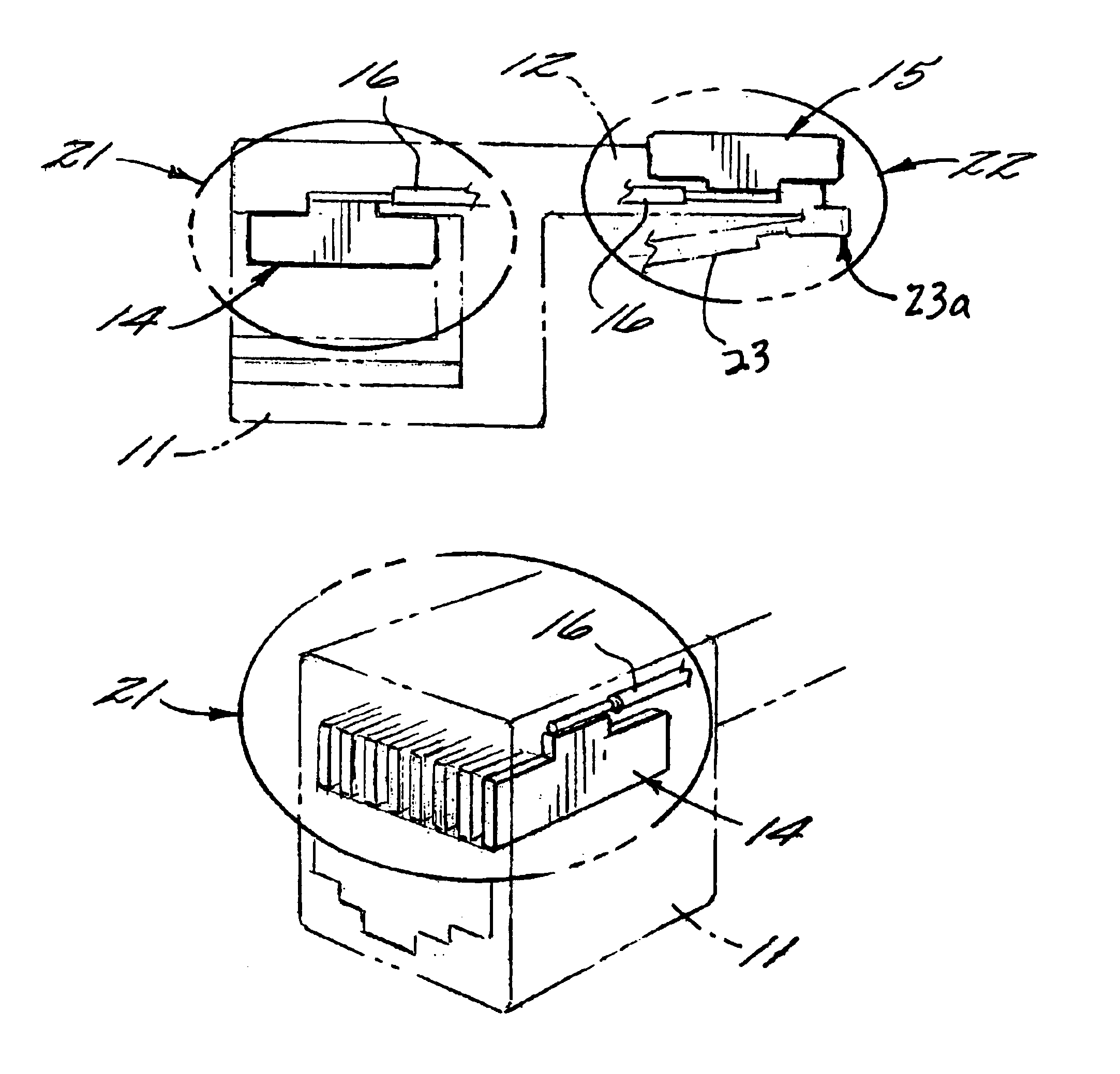
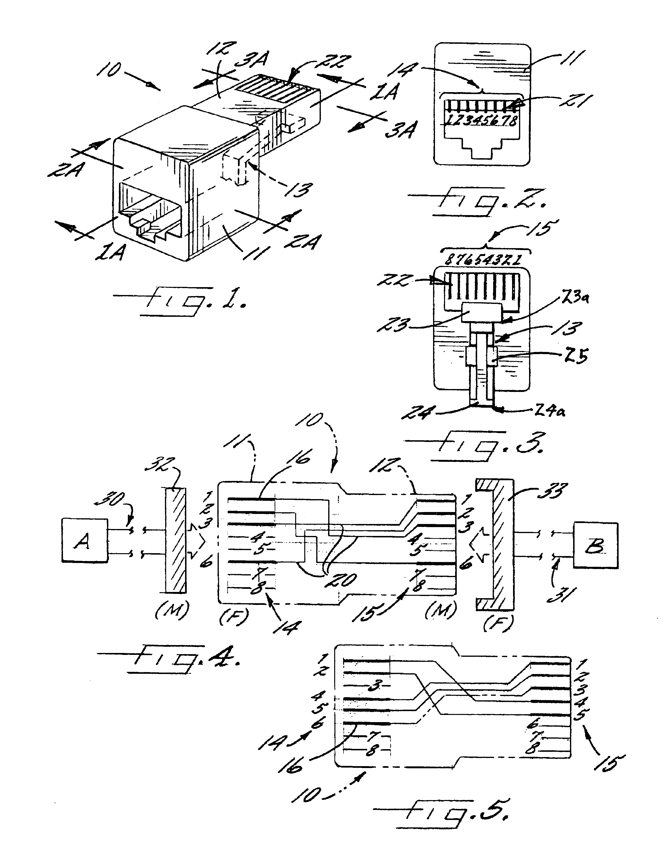
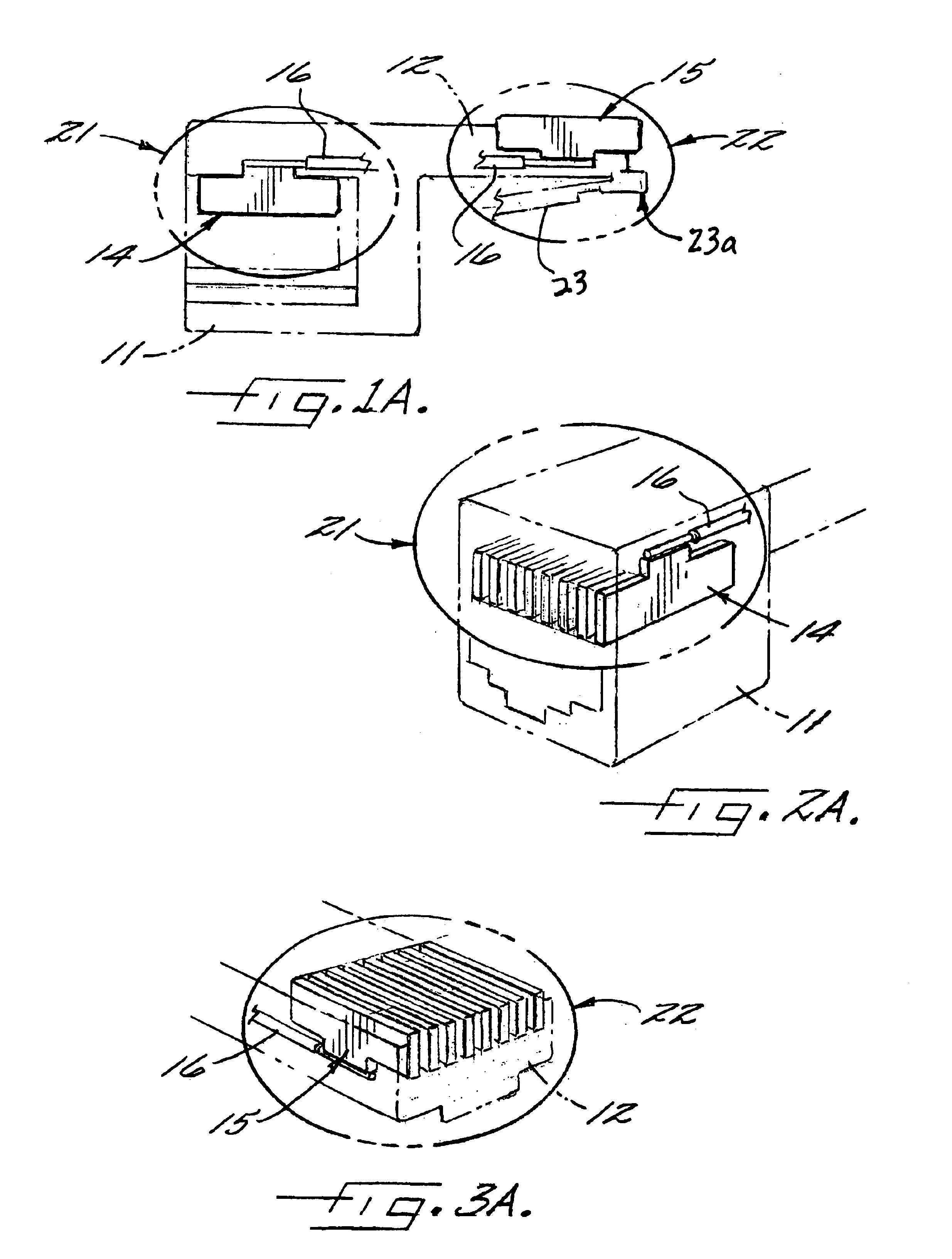
An overall view of the cross-connector 10 which incorporates features of the present invention is set forth in FIG. 1. As used herein, the term “Ethernet network” is used to describe a local area network having any number of communication devices (e.g., router or switch) that communicate based on the protocol defined by the Institute of Electrical and Electronics Engineers (IEEE), namely IEEE 802.3, and that are connected by communication lines (e.g., cables, tw...


PUM


Abstract

A cross-connector capable of connecting communication lines between a variety of communication devices comprises in one embodiment a first housing having eight primary leads, a second housing having eight secondary leads, a plurality of conductive paths within the first and second housings that connect at least one primary lead to at least one secondary lead, and an actuator for releasably securing the cross-connector to a communication device. A communication network that incorporates the cross-connector comprises in one embodiment a first communication device, a second communication device, a cross-connector that connects the first and second communication devices, a first network cable that connects the first communication device to the cross-connector, and optionally, a second network cable that connects the second communication device to the cross-connector.

Description

FIELD OF THE INVENTIONThe invention relates to an apparatus for cross-connecting communication devices. In particular, the invention relates to a cross-connector capable of connecting multiple communication devices in an Ethernet network such as routers, switches, hubs, and personal computers that minimizes the space required for a local network and facilitates test and evaluation procedures. In another embodiment, the invention is used on conjunction with T1 data network installations.BACKGROUND OF THE INVENTIONEngineers created the original Ethernet network by physically cabling multiple communication devices together (e.g., a personal computer and printer). The original Ethernet described communication over a single cable shared by all devices on the network. Thus, once a device was attached to the cable, it could communicate with any other attached device. Unfortunately, a single shared cable limits the size of the Ethernet network. In later stages of development, engineers inco...

Claims


Application Information

Patent Timeline
IPC IPC(8): H01R33/00H01R33/94H01R31/06
CPCH01R33/94H01R31/06H01R24/64Y10S439/941
Inventor CHIMIAK, WILLIAM J.
Owner CHIMIAK WILLIAM J
Why Eureka
Try Eureka