Switching regulator and power supply using the same

a technology of switching regulator and power supply, which is applied in the direction of power supply lines, dc-dc conversion, power conversion systems, etc., can solve the problems of unnecessarily consuming electric power and unable to completely exhibit the soft start function, so as to prevent a rush current and soft start

Inactive Publication Date: 2005-02-01
DENSO CORP
View PDF8 Cites 30 Cited by
  • Summary
  • Abstract
  • Description
  • Claims
  • Application Information

AI Technical Summary

Benefits of technology

An object of the present invention is to provide a switching regulator and power supply using the same which can softly start, i.e., prevent a rush current from flowing into them, always when necessary.
Particularly, if a series regulator is employed as the secondary regulator, an output with high voltage accuracy is obtained with a small power loss from the series regulator, whereby the power source apparatus becomes of high voltage accuracy and low power consumption.

Problems solved by technology

This is because the electric power is unnecessarily consumed by the above-mentioned transistor.
In general, the rush current is generated, when a sudden voltage change is caused when starting up the power supply, by a delayed and excessive control when a feed-back system for generating the PWM signal cannot follow that sudden voltage change.
However, the conventional soft start circuit 37 has a disadvantage that it cannot completely exhibit the soft start function against the above-mentioned short-time-period voltage drop, because the conventional soft start circuit 37 may fail to discharge rapidly enough all the stored charges during the above-mentioned short time period.
Therefore, the conventional switching regulator and power supply using the same has a disadvantage that it may possibly allow the rush current in I1 to flow, as shown in FIG.

Method used


Image

  • Switching regulator and power supply using the same
  • Switching regulator and power supply using the same
  • Switching regulator and power supply using the same

Examples


embodiment 1

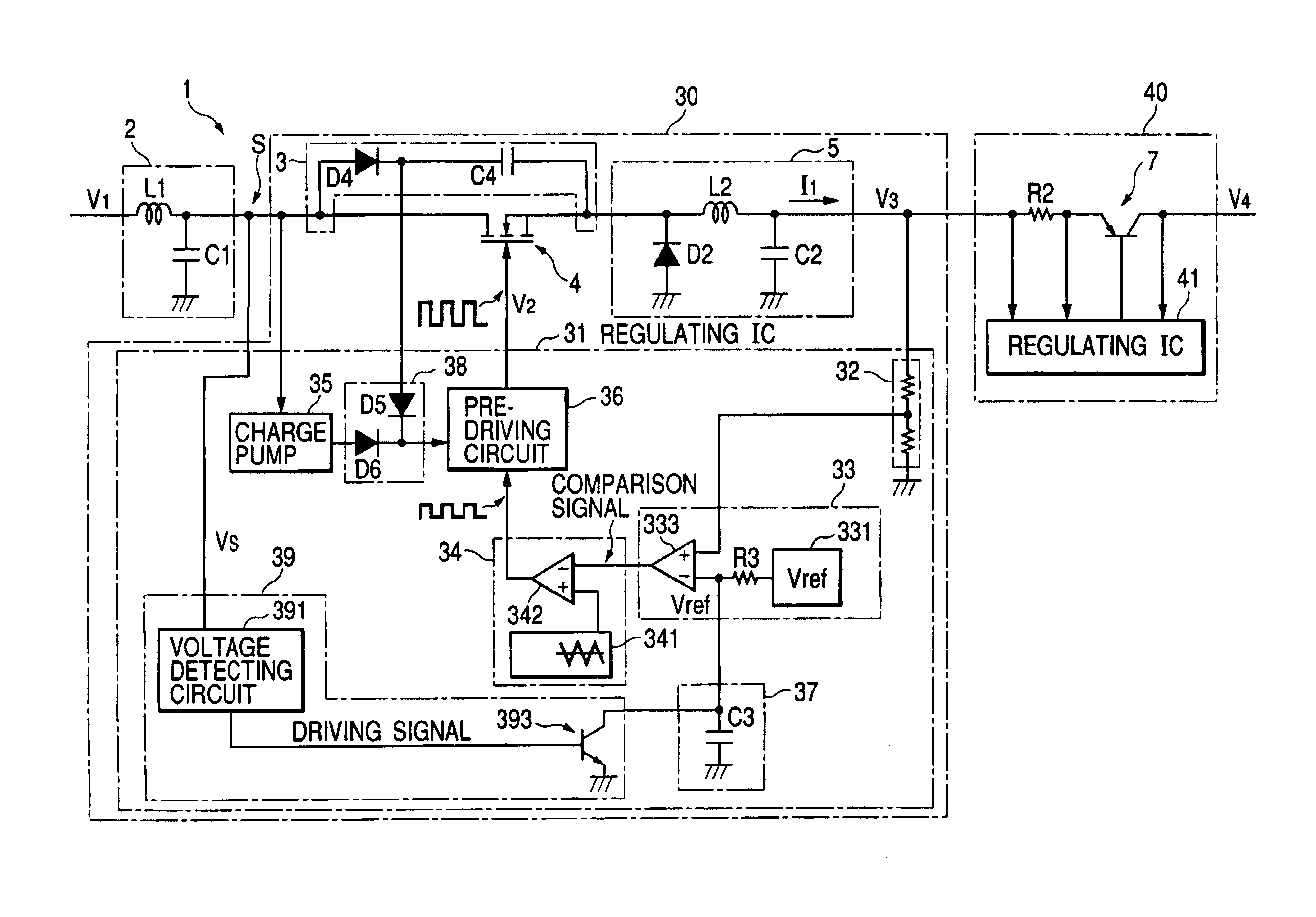
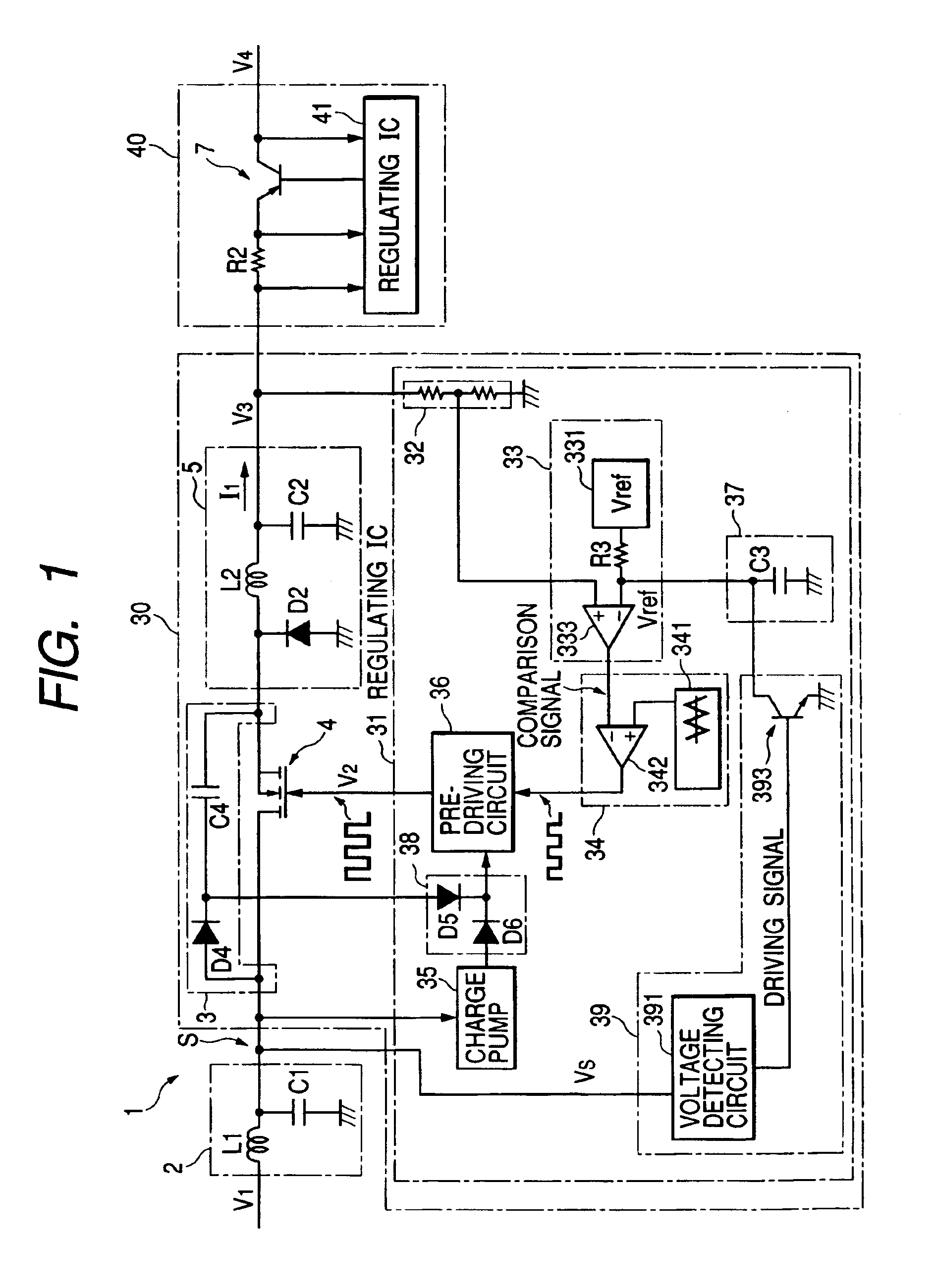
FIG. 1 is a circuit diagram of the power supply 1 of Embodiment 1 of the present invention. The similar reference numerals are given to the similar elements as those in the conventional power supply 101 as shown in FIG. 7.

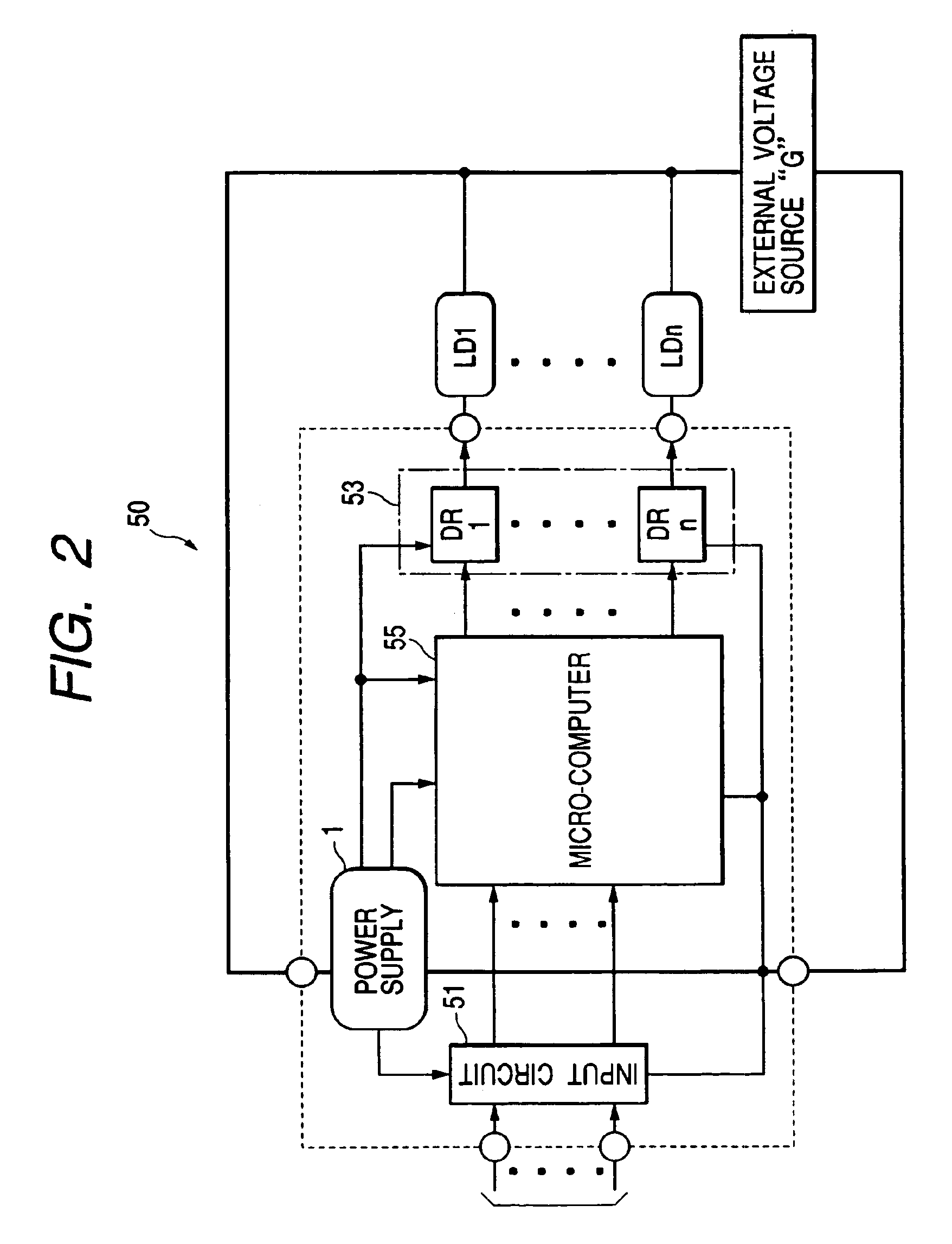
FIG. 2 is a block diagram of a vehicle control apparatus 50 including the power supply 1 as shown in FIG. 1. The vehicle control apparatus as shown in FIG. 2 comprises: an input circuit 51 including a filter and analog-to-digital (AID) converter for receiving signals from sensors disposed outside the vehicle control apparatus 50 and other signals; driving circuits 53 (DR1 to DRn) which is supplied by an external voltage source G and drives electrical loads LD1 to LDn; a micro-computer 55 which executes various calculations on the basis of the signals inputted from the input circuit 51 in order to obtain instructions for the driving circuits 53; and the power supply 1 for supplying the elements 51 to 55 with prescribed voltages.

Here, the external voltage from the ex...

embodiment 2

FIG. 5 is a circuit diagram of the power supply 1b of Embodiment 2 which is different from Embodiment 1, only in that a regulating IC 31b comprises: a new soft start circuit 37b and new function recovering circuit 39b. The similar reference numerals are given to the similar elements in Embodiment 2 and 1 (FIGS. 5 and 1).

As shown in FIG. 5, the regulating IC 31b comprises a new soft start circuit 37b and new function recovering circuit 39b, as well as the same elements as Embodiment 1 such as the voltage dividing circuit 32; comparison signal generating circuit 33; PWM circuit 34; charge pump 35; pre-driving circuit 36; and supply voltage selecting circuit 38.

The new soft start circuit 37b comprises: a pulse generating circuit 371 for generating a pulse train during a prescribed time period after turning on the power supply 1b; and a transistor 373 which is turned on and off in accordance with the pulse train. The collector of the transistor 373 is connected with the signal line at a...


PUM


Abstract

The power supply PS includes a voltage detecting circuit VD for detecting a voltage level Vs inputted from an external voltage source, a boot strap circuit BS, andET connected in parallel with BS, a smoothing circuit SM connected with the BS output terminal and a regulating IC connected with BS and FET. The regulating IC includes VD, a transistor Tr and condenser C. Both when a PS switch is turned on and when VD detects that Vs (which once descended) reaches an ascending reference, a high level driving signal generated by VD is changed into a low level signal, thereby turning off Tr connected with C. Thus, until Tr completes charging up C, a duty ratio of a pulse width modulation (PWM) signal dependent on the SM output is made gradually greater, thereby surely preventing a rush current by turning on and off the FET by the PWM signal.

Description

BACKGROUND OF THE INVENTION1. Field of the InventionThe present invention relates to a switching regulator and power supply using the same.2. Description of the Related ArtOne of the conventional switching regulator or series regulator for use in supplying a stabilized constant voltage by lowering a voltage inputted from an external voltage source is disclosed in, e.g., JP9-37545A, 1997, paragraphs 0002 to 0004, FIGS. 2 and 3.In the conventional switching regulator, the stabilized constant voltage is obtained by switching on and off a transistor connected in series with a current route from the external voltage source, thereby supplying a smoothing circuit with a required electric power only. Therefore, a loss of the electric power is smaller, although an accuracy in the outputted voltage is lower.On the other hand, in the conventional series regulator, the stabilized constant voltage is obtained by increasing and decreasing a driving power of a transistor connected in series with t...

Claims


Application Information

Patent Timeline
Patent Type & Authority Patents(United States)
IPC IPC(8): H02M1/00H02M3/00G05F1/10
CPCH02M1/36Y10S323/908Y10S323/901
Inventor ITABASHI, TORUISHIKAWA, TAKANORINAGATA, JUNICHI
Owner DENSO CORP
Why Eureka
Try Eureka