
Handcuffs

Inactive Publication Date: 2005-02-08
KIM KI SUK +1
View PDF13 Cites 34 Cited by
  • Summary
  • Abstract
  • Description
  • Claims
  • Application Information

AI Technical Summary

Benefits of technology

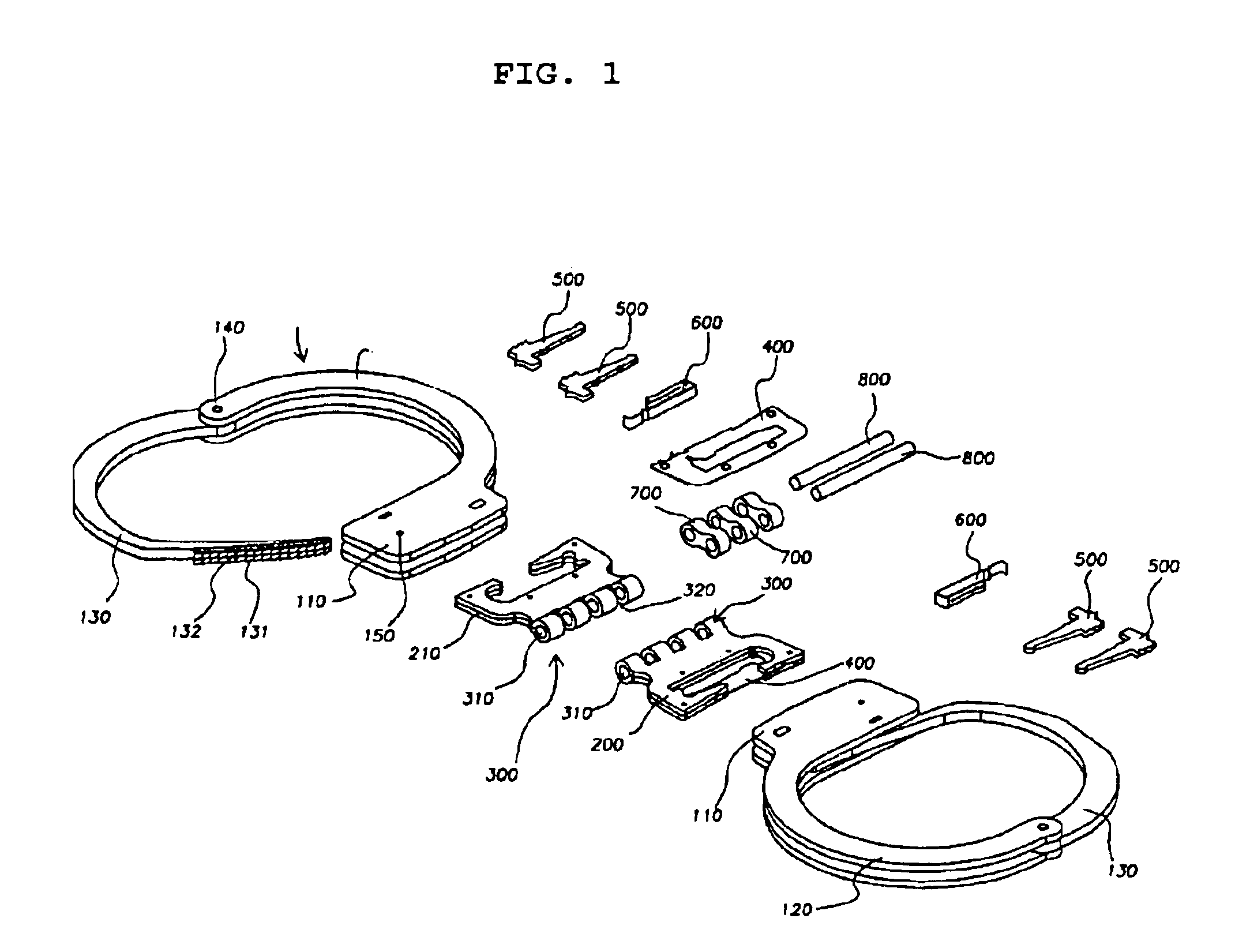
A further object of the present invention is to provide a handcuff having a partition plate interposed between the integrally formed frame plate through a slit for partition, so that the partition plate can be assembled quickly into the frame plate and fixed therein securely, and consequently the teeth of a ratchet portion of a movable arm can be securely engaged with pawl pieces included in the base bodies.
A further object of the present invention is to provide handcuffs which cannot be picked or disassembled by an external impact or an unwanted insertion of a foreign metal object.
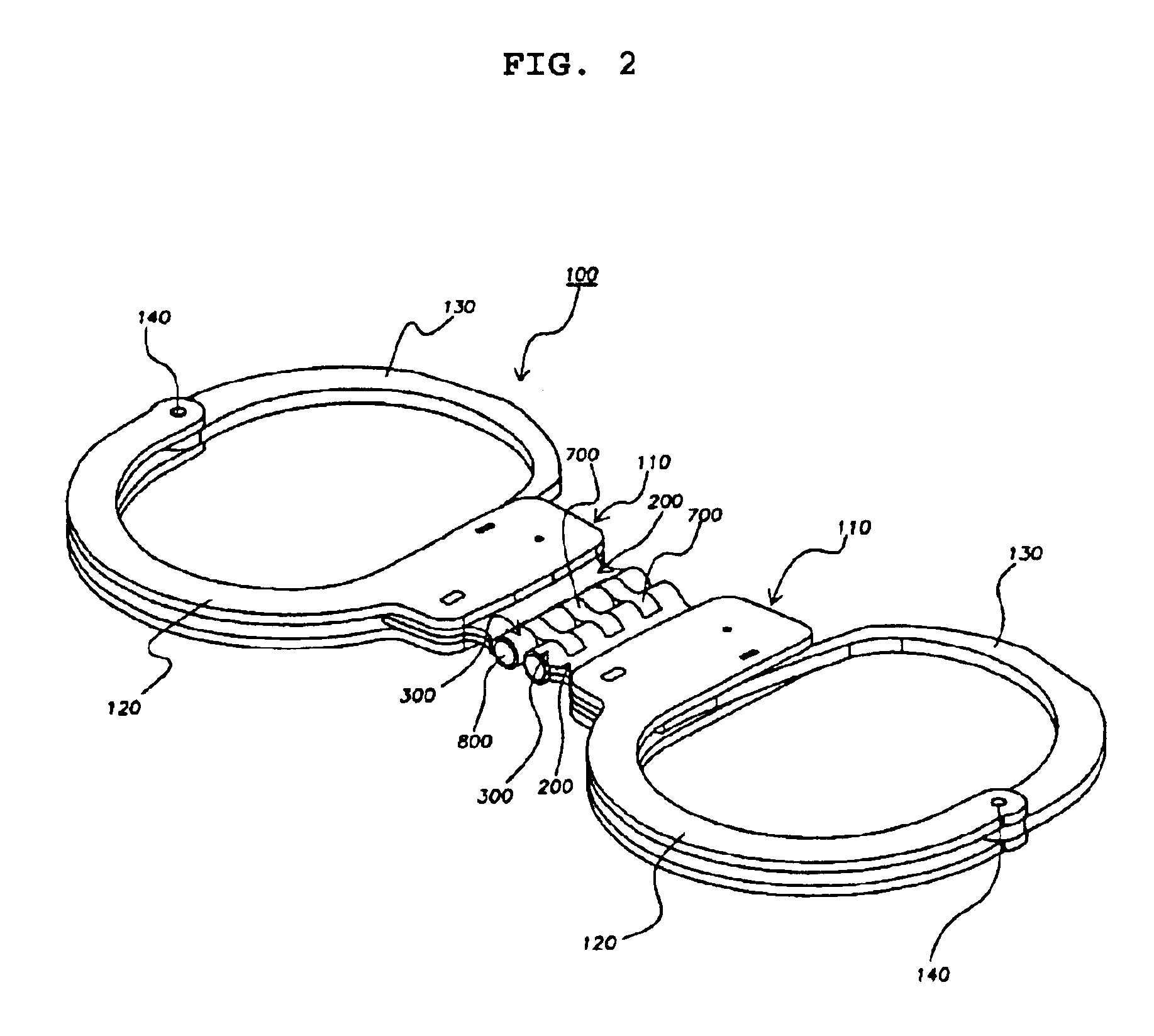
Further, each of the couplings having openings at its both ends is fitted into the grooves formed between the neighboring hinge members, and the hinge axis is alternately fitted into the openings of the hinge members and the openings of the couplings, so that the pair of handcuffs can move smoothly and can be foldable around the connecting structure.

Problems solved by technology

Accordingly, due to the cast-iron formation, the weight of the handcuffs becomes increased and it is inconvenient to carry along the handcuffs.
Also, the productivity and workability of the handcuffs are remarkably deteriorated due to the cast-iron formation method, and thus the manufacturing cost of the handcuffs is increased.

Method used


Image

  • Handcuffs
  • Handcuffs
  • Handcuffs

Examples


Embodiment Construction

Reference will now be made in detail to a preferred embodiment of the present invention in conjunction with the accompanying drawings.

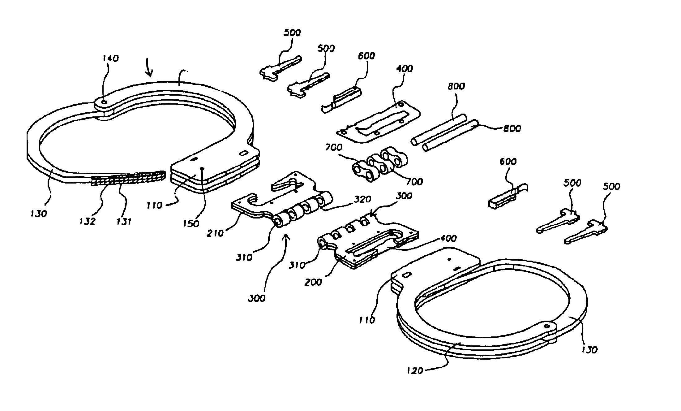
The handcuffs according to the present invention comprises a pair of handcuff parts (100) and a connecting structure,each of the handcuff parts (100) comprising rectangular base bodies (110) which accommodate both ends of a frame plate (200), a partition plate (400) interposed between the ends of the frame plate (200), a pair of pawl pieces (500) and a leaf spring (600) therein; a movable arm (130) formed in a semi-circle shape, which is provided at its free end with a ratchet portion formed with dual line of teeth (131); and a pair of fixed arms (120) formed in a semi-circle shape, which are pivotably connected at free ends thereof to the other end of the movable arm (130) by a pivot pin (140) and are integrally provided at their other ends with the base bodies (110), andthe connecting structure comprising two frame plates (200), each of which includ...


PUM


Abstract

The present invention relates to a pair of handcuffs which cannot be disassembled easily by securing a firm connection therebetween by hinge members. The handcuffs according to the present invention are made by the methods of shearing and bent-up forming in replacement of the conventional cast-iron method, and are connected by a connecting structure which comprises two frame plates, each of which includes a plurality of hinge members forming grooves between the neighboring hinge members and having openings therethrough and also includes a pair of flat members; couplings fitted into the grooves of the hinge members; and hinge axes to be axially fitted into the openings of the hinge members and the couplings.

Description

FIELD OF THE INVENTIONThe present invention relates to a set of handcuffs which are connected to each other by hinge members, and more particularly to a pair of handcuffs which are foldable centering around the hinge members and cannot be disassembled easily by securing a firm connection by means of hinge members which are connected by a plurality of couplings.BACKGROUND OF THE INVENTIONConventionally, each of a pair of handcuffs comprises two rectangular base bodies which accommodate frame plates, a partition plate between the frame plates, a pair of pawl pieces and a leaf spring therein; a movable arm formed in a semi-circle shape, which is provided at its free end with a ratchet portion formed with dual line of teeth; and a pair of fixed arms formed in a semi-circle shape, which are pivotably connected at free ends thereof to the other end of the movable arm by a pivot pin and are integrally provided at their other ends with the rectangular base bodies, wherein the dual line of t...

Claims


Application Information

Patent Timeline
IPC IPC(8): E05B75/00
CPCE05B75/00Y10T70/404
Inventor KIM, KI SUKKWON, JEONG SU
Owner KIM KI SUK
Learn More