Cutting table fence

a technology of cutting table and fence, which is applied in the field of cutting guide, can solve the problems of high degree of accuracy not being maintained, complex and difficult to install mechanisms, and both are relatively complex

Inactive Publication Date: 2005-02-08
KENNELLY JOHN P
View PDF11 Cites 33 Cited by
  • Summary
  • Abstract
  • Description
  • Claims
  • Application Information

AI Technical Summary

Problems solved by technology

However, a high degree of accuracy has not been maintained, at least not without involving complex and difficult to install mechanisms.
Such mechanisms most often result in a practically permanent installation of the fence on the saw, since removal and remounting of the fence is most often a laborious, time consuming chore.
The above examples of cable and pulley mounted fences operate well to hold a fence in accurate position on across a table surface, but both are relatively complex.
Also neither of the above apparatus are easily removable from the cutting table when use requires removal of the fence.

Method used


Image

  • Cutting table fence
  • Cutting table fence
  • Cutting table fence

Examples


Embodiment Construction

This disclosure of the invention is submitted in furtherance of the constitutional purposes of the U.S. Patent Laws “to promote the progress of science and useful arts” (Article 1, Section 8).

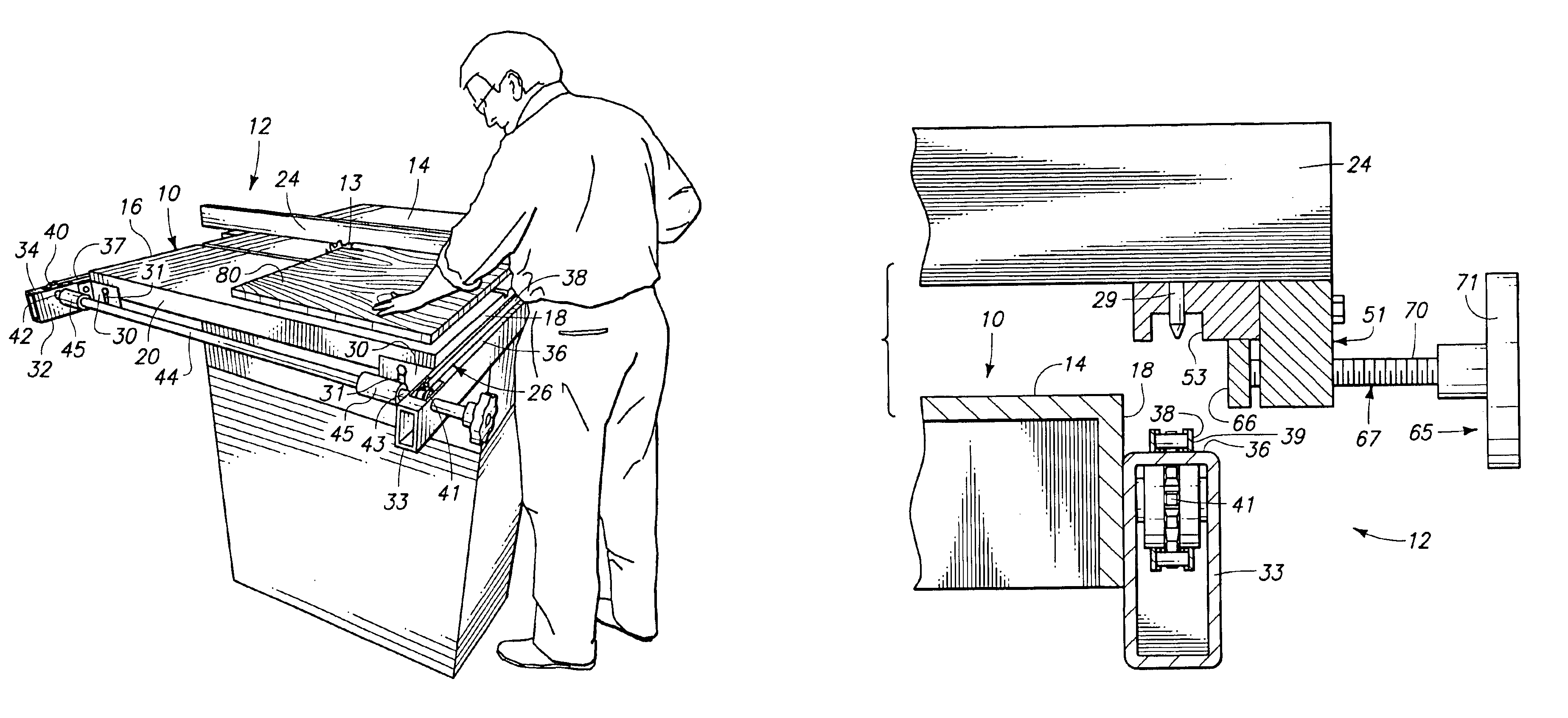
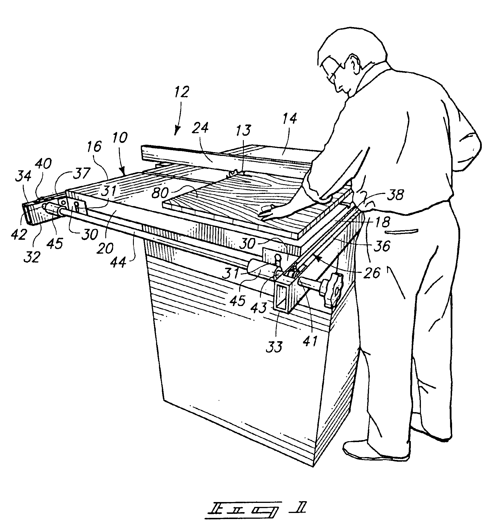
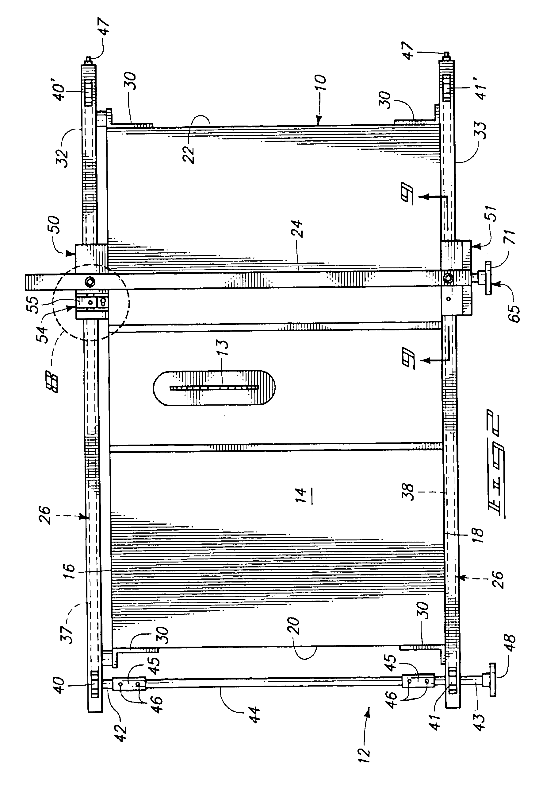
In general reference to FIG. 1 of the drawings, a cutting table is shown as identified by the reference numeral 10. The particular cutting table 10 exemplified is a table saw of the type commonly used in the woodworking industry. Other types of cutting tables may also be used with the present fence, which is generally shown at 12.

The exemplary table 10 includes a table top with a substantially planar top surface 14 and substantially parallel forward and rearward side edges 16, 18. The size and configuration of the table top may vary according to the nature of the cutting device, but typically is rectangular and the edges 16, 18 are usually substantially parallel. The edges 16, 18 are joined by side edges 20, 22 that are also substantially parallel and perpendicular to the forward and rearward e...


PUM

PropertyMeasurementUnit
specific angleaaaaaaaaaa
widthaaaaaaaaaa
rotationaaaaaaaaaa

Abstract

A fence is described for attachment to a cutting table or in combination with a cutting table. The fence includes pair of elongated guide rails with brackets configured to be mounted to the cutting table. An endless chain is provided on each guide rail, trained about sprockets rotatably mounted on the guide rail. Each chain includes a working flight that extends along the associated guide rail. Each chain further includes sprocket tooth receiving spaces. A shaft interconnects, one of the sprockets on one guide rail with one of the sprockets on the remaining guide rail such that rotation of the shaft will result in all the sprockets rotating in unison, causing uniform and equal movement of the chain. An elongated cutting guide is provided with aligning lugs that are releasably received within selected tooth receiving spaces of the chains in such a manner that the cutting guide may be selectively engaged with the chains and lifted from the chains. A locking mechanism is configured to secure the cutting guide in a selected position along the working flights of the chains.

Description

TECHNICAL FIELDThe present invention relates to cutting guides in general and more particularly to a removable fence for a cutting table.BACKGROUND OF THE INVENTIONNumerous fence designs have been produced for the cutting tables of various cutting tools such as woodworking table saws. The fence on a table saw is used, in general, to hold an edge of a workpiece at a specific angle, usually parallel to a cutting blade 13. The fence must be held parallel to the blade to minimize the kerf width, and to avoid dangerous “kick-back.” A precisely parallel fence also is a significant factor in cutting accuracy.Much of recent development in design of fences for cutting tables has focused on accuracy, or the ability for the fence to maintain an accurate state of parallelism with the saw blade. However, a high degree of accuracy has not been maintained, at least not without involving complex and difficult to install mechanisms. Such mechanisms most often result in a practically permanent instal...

Claims


Application Information

Patent Timeline
Patent Type & Authority Patents(United States)
IPC IPC(8): B27B27/02B27B27/10B27B27/00
CPCB27B27/10B27B27/02Y10T83/727Y10T83/7647Y10T83/773
Inventor KENNELLY, JOHN P.LINN, JACK A.
Owner KENNELLY JOHN P
Why Eureka
Try Eureka