Pocket-dampening lacrosse head

a lacrosse head and pocket technology, applied in the field of lacrosse sticks, can solve the problems of hard control, hard catch and control of balls, and the failure of the monolithic double wall head to outperform the wooden head, and achieve the effects of reducing the rebound of the pocket, dampening the limit of the movement of the ball, and being easy to control and retain

a lacrosse head and pocket technology, applied in the field of lacrosse sticks, can solve the problems of hard control, hard catch and control of balls, and the failure of the monolithic double wall head to outperform the wooden head, and achieve the effects of reducing the rebound of the pocket, dampening the limit of the movement of the ball, and being easy to control and retain

US6852047B2Inactive Publication Date: 2005-02-08WM T BURNETT IP

Image

  • Pocket-dampening lacrosse head
  • Pocket-dampening lacrosse head
  • Pocket-dampening lacrosse head

Examples


Embodiment Construction

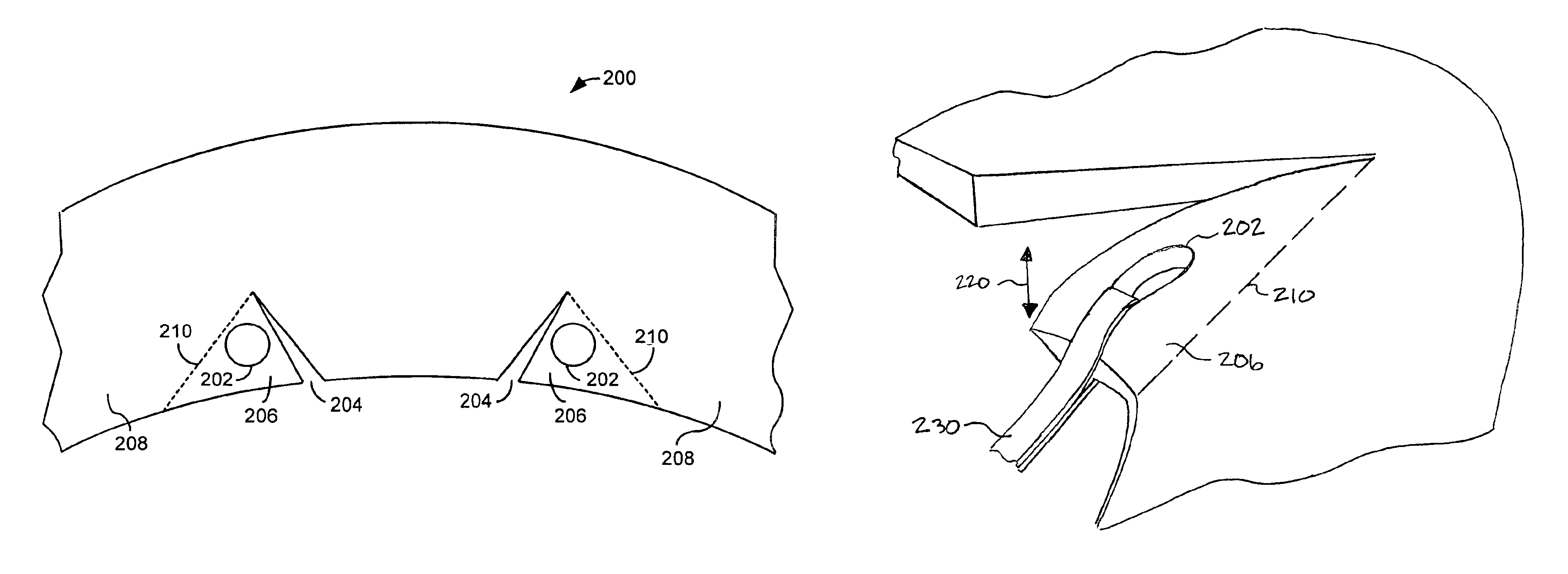
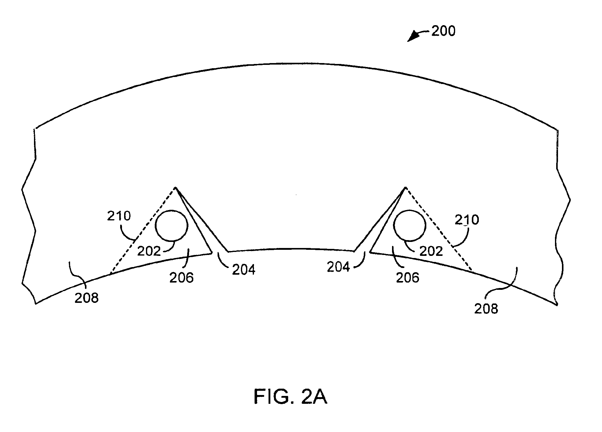
The present invention is a method and apparatus for absorbing the energy of a lacrosse ball moving into and within a lacrosse head pocket. FIG. 2A shows an embodiment of the invention, which includes a lacrosse head frame 200 having a thread hole 202 and an aperture 204. Thread hole 202 is located anywhere on lacrosse head frame 200 (e.g., ball stop, sidewalls, or scoop) and receives a string or thong of a pocket that is attached to frame 200. Although shown as a circle, thread hole 202 could, of course, be of any shape (e.g., an oval or slit) suitable for receiving a pocket thread. Aperture 204 is proximate to thread hole 202, such that frame 200 is separated into a moveable structure 206 and a rigid frame structure 208. Moveable structure 206 encompasses at least a portion of thread hole 202 and moves relative to rigid frame structure 208. In this example, the boundary between moveable structure 206 and rigid frame structure 208 is flex line 210, due to the position of aperture 20...


PUM


Abstract

A method and apparatus for dampening the rebound of a lacrosse head pocket. In one embodiment, the apparatus includes a frame having a thread hole and an aperture proximate to the thread hole. The aperture creates a moveable structure of the frame. The moveable structure encompasses at least a portion of the thread hole. The moveable structure is adapted to flex relative to the frame.

Description

BACKGROUND1. Field of the InventionThe present invention relates generally to lacrosse sticks, and more particularly, to an apparatus and method for dampening the rebound of a lacrosse head pocket after the pocket has been pulled taut by, for example, a caught, thrown, or cradled lacrosse ball.2. Background of the InventionSince they were first introduced around 1970, double-wall, synthetic lacrosse heads have revolutionized the game of lacrosse. In comparison to the early single-wall wooden lacrosse heads, synthetic heads offer vastly improved feel, balance, lightness, maneuverability, and flexibility. The synthetic heads are also less expensive to manufacture and can be produced with a more consistent level of quality. And, perhaps most importantly, the synthetic heads offer superior durability, withstanding the harsh impacts and bending encountered during play, such as during face-offs and defensive checking.FIG. 1 illustrates a conventional molded-head lacrosse stick. As shown, ...

Claims


Application Information

Patent Timeline
08 Feb 2005
Publication
US6852047B2
IPC
A63B59/00; A63B59/02
CPC
A63B59/02; A63B59/0088; A63B2243/005; A63B59/20; A63B60/50; A63B2102/14; A63B60/54
Inventors
TUCKER, SR., RICHARD B. C.