
RFID system and method for ensuring personnel safety

a technology of personnel safety and rfid, applied in the field of personnel safety, can solve the problems of rudimentary system, no automated process or system for ensuring personnel safety,

Inactive Publication Date: 2005-02-08
TERRESTRIAL COMMS LLC
View PDF43 Cites 297 Cited by
  • Summary
  • Abstract
  • Description
  • Claims
  • Application Information

AI Technical Summary

Benefits of technology

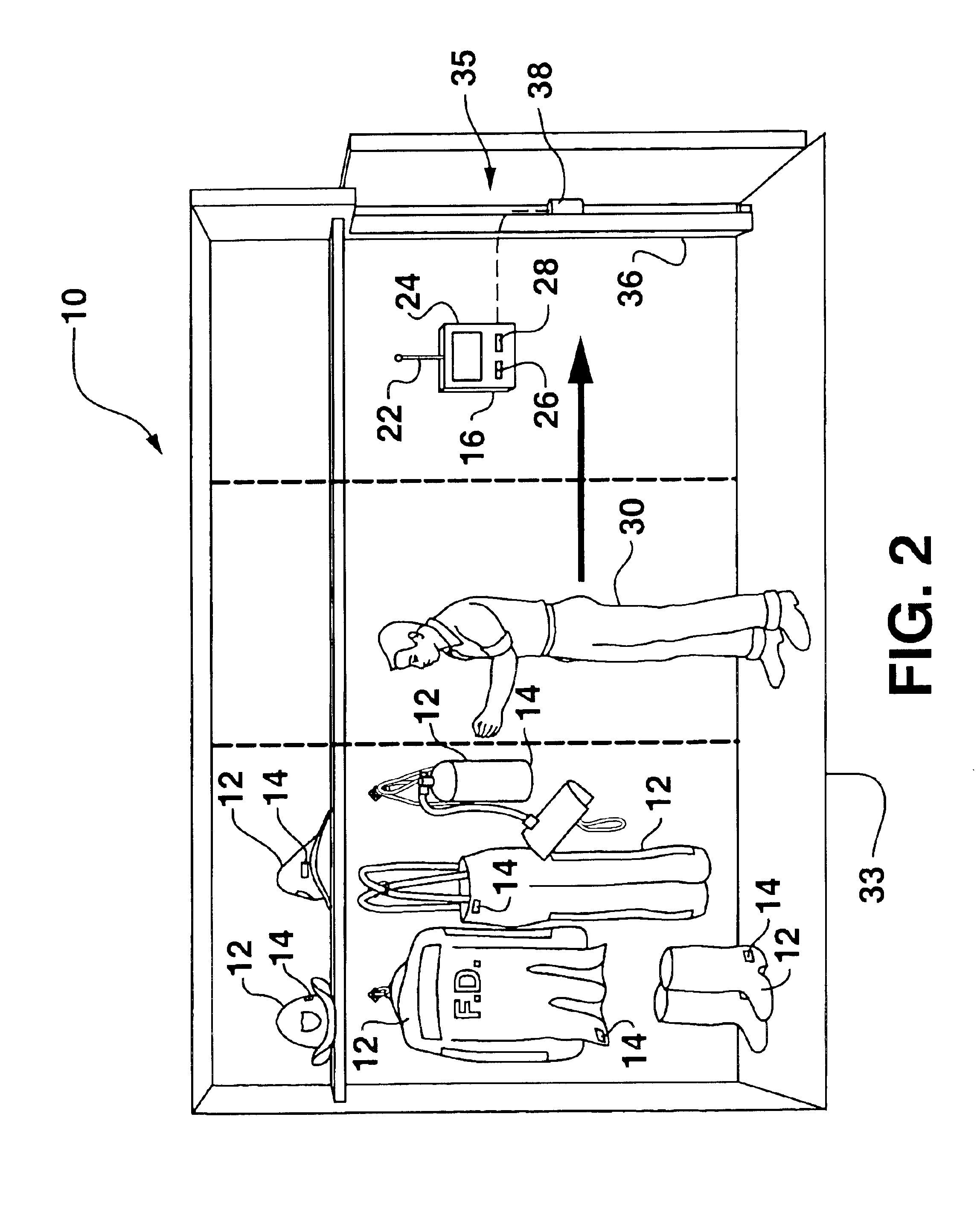
In an alternate embodiment, the scanner may be disposed at the exit of a given location. For example, a hospital locker/dressing room area, firehouse locker room, operating room prep area, military installation ready room, and the like. In these scenarios the procedure or task to be performed by the individual is beyond or outside of the controlled area, and the system ensures that the individual has the required necessary equipment prior to leaving the area. For example, the system may be incorporated in a firehouse dressing area to ensure that firemen or other rescue personnel are properly equipped prior to leaving the station.
In an alternate embodiment, a smart tag is associated with the individual and contains information identifying the individual. In this manner, particular individuals are identified by the scanner at the accountability location. With this embodiment, an electronically stored databa

Problems solved by technology

Presently, there does not exist an automated process or system for ensuring that personnel wear the required articles and adhere to safety precautions regarding protective gear, clothing, and the like.
There are obvious drawbacks to this rudimentary system.

Method used


Image

  • RFID system and method for ensuring personnel safety
  • RFID system and method for ensuring personnel safety
  • RFID system and method for ensuring personnel safety

Examples


Embodiment Construction

Reference will now be made in detail to one or more embodiments of the invention, examples of which are graphically illustrated in the drawings. Each example and embodiment are provided by way of explanation of the invention, and not meant as a limitation of the invention. For example, features illustrated or described as part of one embodiment may be utilized with another embodiment to yield still a further embodiment. It is intended that the present invention include these and other modifications and variations.

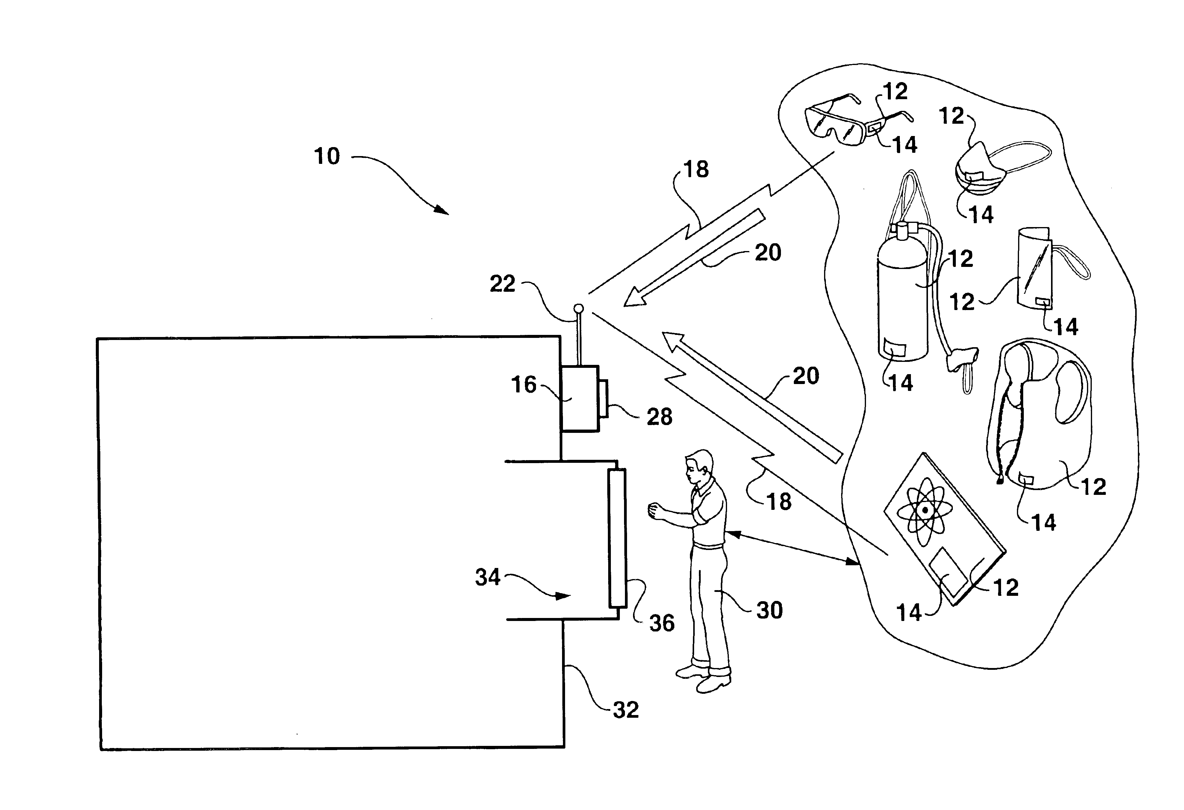
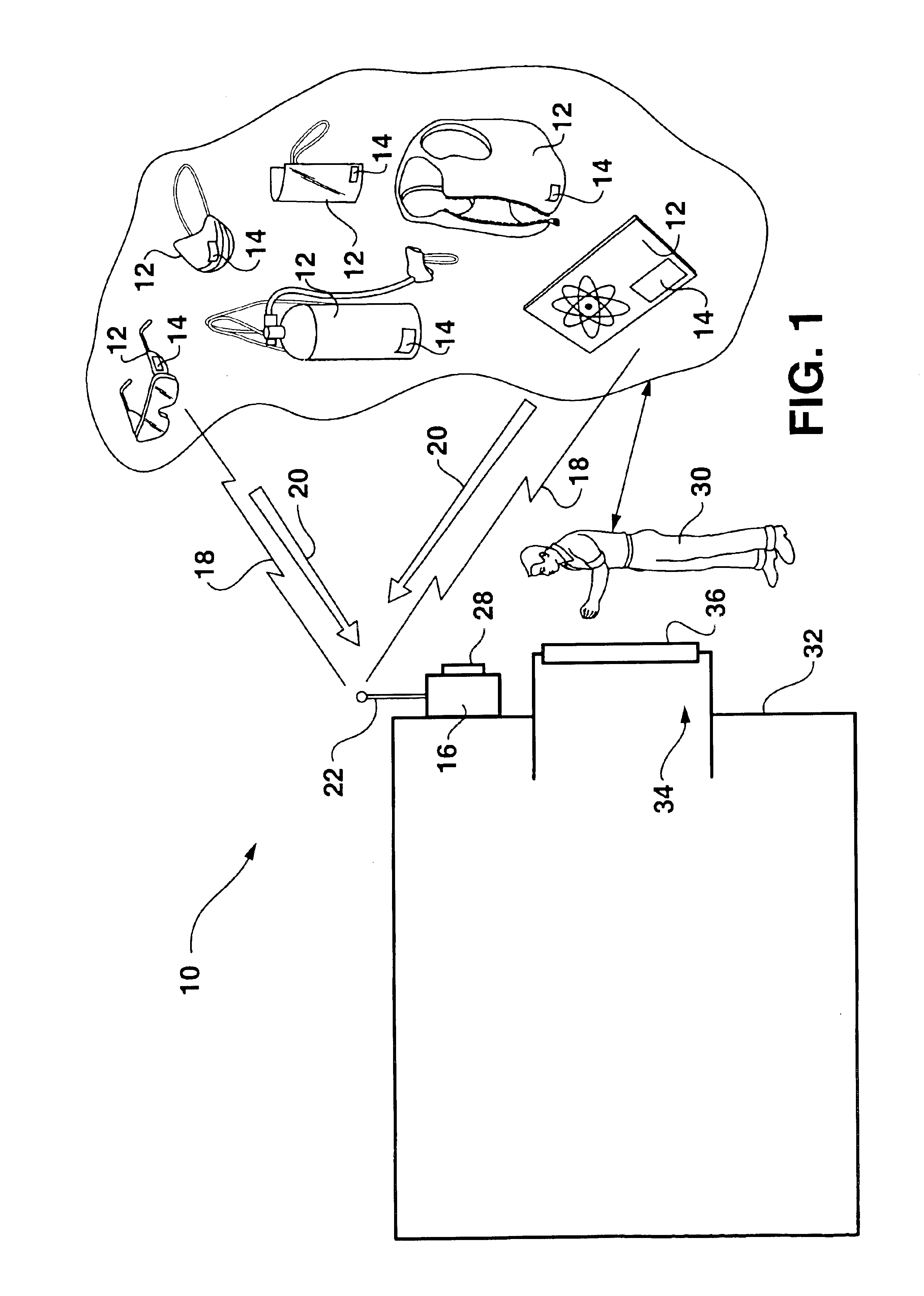
FIG. 1 graphically illustrates conceptual aspects of a method and system 10 according to the invention. Any type or variation of equipment 12 that is required to be worn or donned by an individual 30 prior to performing a particular task or work function is provided with a smart tag 14. It should be appreciated that the invention is not limited to any particular category or type of equipment 12, but generally encompasses all types of safety gear, protective clothing, assist...


PUM


Abstract

A RFID method and system are provided for ensuring that personnel are properly outfitted with necessary equipment for performance of a particular task or procedure. RFID smart tags are configured with the required pieces of equipment, the smart tags containing information to identify their respective pieces of equipment. A RFID scanner is disposed at a location through which an individual passes prior to performance of the procedure. The scanner interrogates the smart tags and determines if the individual has all of the required pieces of equipment.

Description

TECHNICAL FIELD OF THE INVENTIONThe present invention relates generally to the field of personnel safety, and more particularly to a system and method for ensuring the safety of personnel in areas requiring protective gear, clothing, and the like.BACKGROUNDRadio Frequency Identification Devices (RFIDs) are low-cost, passive “smart” chips or “tags” that can be embedded in or attached to articles, products, and the like, to convey information about the product via a scanner. The smart tags are generally small labels or the like with a miniature embedded antenna. The tags may be passive or active, the active tags requiring an internal power supply. A reader or scanner interrogates the smart tag with an electronic “trigger” signal. The tag in turn generates an electromagnetic pulses response that is readable by the scanner, the response containing the product information. RFID smart tags can be embedded in or attached to product packaging, or incorporated directly into the product, and ...

Claims


Application Information

Patent Timeline
IPC IPC(8): G07C9/00
CPCG07C9/00111G08B21/24G21F3/02G07C9/28
Inventor CHEN, FUNG-JOUREADE, WALTER C.LINDSAY, JEFFREY DEAN
Owner TERRESTRIAL COMMS LLC
Learn More