

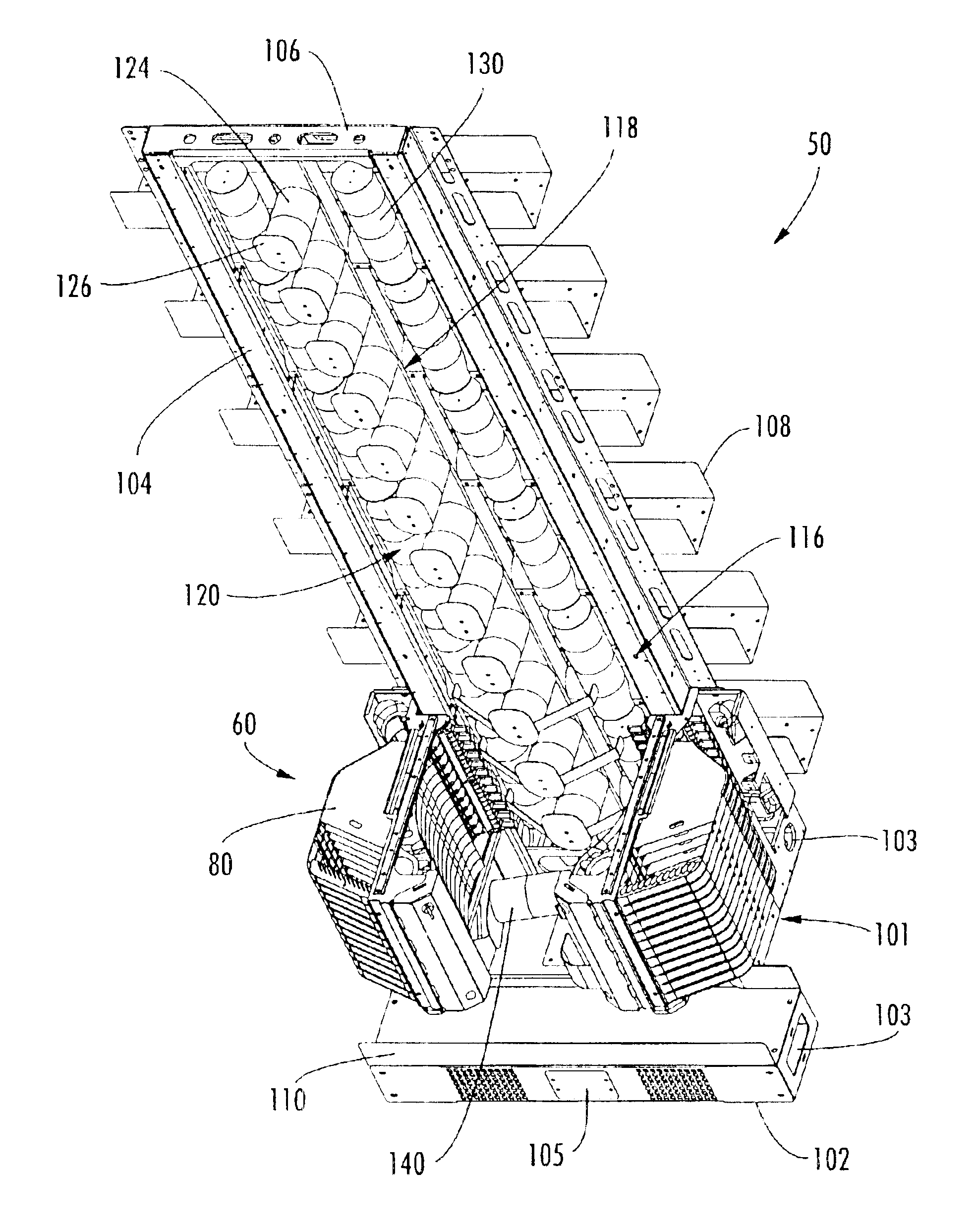
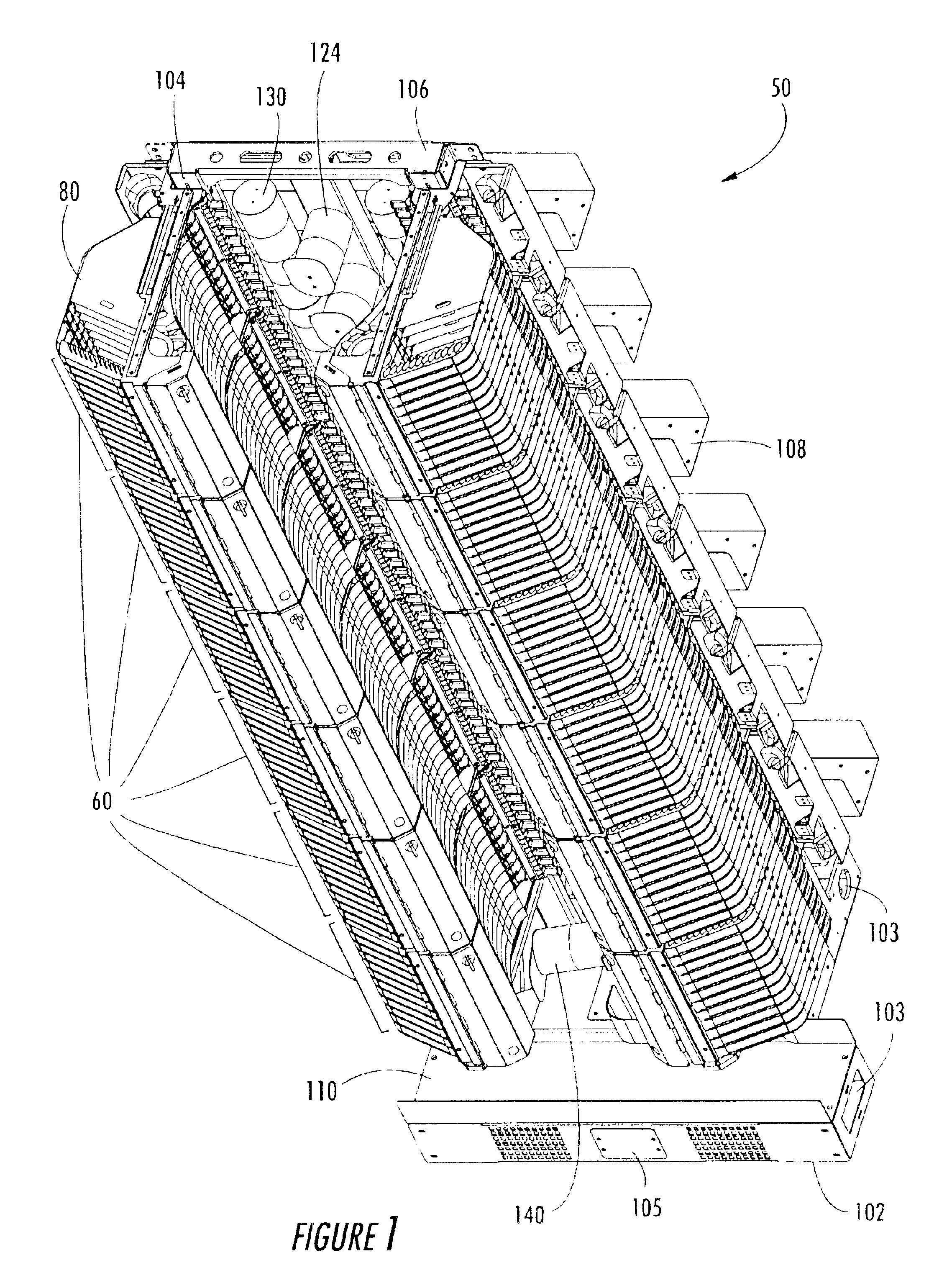
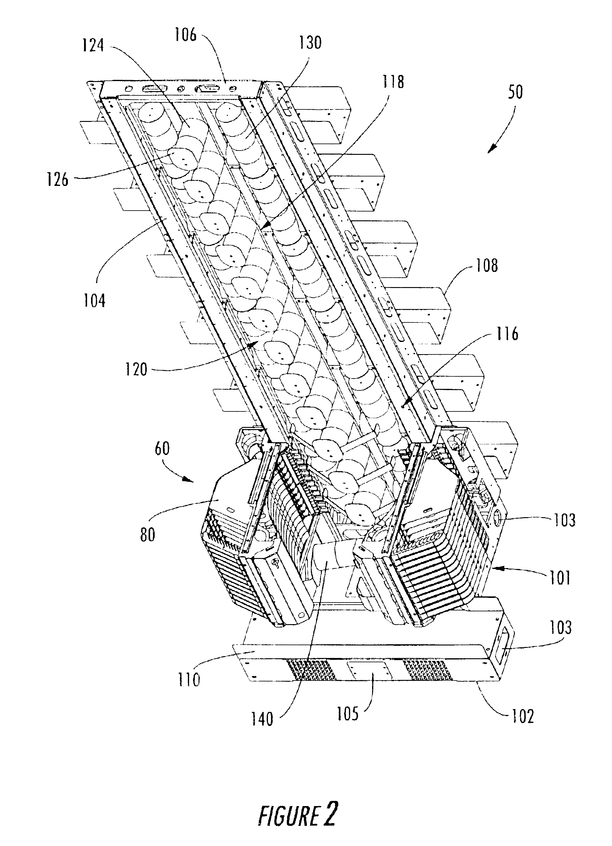
High density fiber optic distribution frame
a high-density fiber optic and distribution frame technology, applied in the direction of optics, fibre mechanical structures, instruments, etc., can solve the problems of not providing the combination of features necessary to address all of the deficiencies, the known distribution frame is typically not compatible with existing fiber optic hardware, and the known high-density fiber optic distribution frame has certain deficiencies
- Summary
- Abstract
- Description
- Claims
- Application Information
AI Technical Summary
Benefits of technology
Problems solved by technology
Method used
Image

Examples
Embodiment Construction
The invention is described in greater detail hereinafter with reference to the accompanying drawings, in which various exemplary embodiments of the invention are shown. The invention may, however, be embodied in many different forms, and therefore, should not be construed as being limited to the embodiments described and shown herein. Exemplary embodiments are set forth herein so that this description will be thorough and complete and will fully convey the best mode and intended scope of the claimed invention, while enabling those skilled in the art to make and practice the invention without undue experimentation. Like reference numerals are utilized throughout the drawing figures to identify the same or similar parts in the embodiments shown and described. However, no particular significance should be afforded the reference numbers. Likewise, no particular significance should be afforded to the relative size or scale of the components depicted in the drawing figures, unless specifi...
PUM
 Abstract
Description
Claims
Application Information