
Online optical cable monitoring device and method for improving alarm accuracy rate

A monitoring device and accuracy rate technology, which is applied in the field of optical cable online monitoring devices, can solve problems such as false alarms, fluctuations in the loss value of fixed event points, and system false alarms, so as to improve accuracy, reduce short-term or instantaneous false alarms, and reduce no warning effect

Active Publication Date: 2013-09-04
STATE GRID CORP OF CHINA +1
View PDF6 Cites 12 Cited by
  • Summary
  • Abstract
  • Description
  • Claims
  • Application Information

AI Technical Summary

Problems solved by technology

The loss monitoring method in the prior art has the following defects: (1) Since the default alarm threshold of the system is only fixed at 1dB, it is prone to false alarms caused by human operation; It is identified as an alarm occurrence, so short-term or instantaneous false alarms are prone to occur; (3) Some original fixed loss points in the OTDR measured curve are prone to false alarms; the loss value of fixed event points is prone to fluctuations

Method used


Image

  • Online optical cable monitoring device and method for improving alarm accuracy rate
  • Online optical cable monitoring device and method for improving alarm accuracy rate

Examples


Embodiment Construction

[0035] The present invention will be further elaborated below by describing a preferred specific embodiment in detail in conjunction with the accompanying drawings.

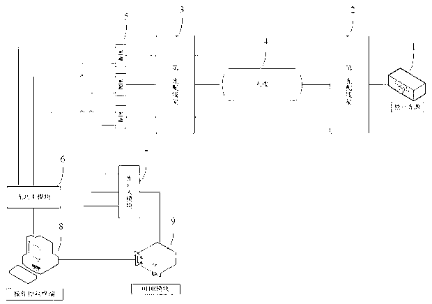
[0036] Such as figure 1 As shown, an optical cable online monitoring device of the present invention includes an independent light source 1, a first optical distribution frame 2 and a second optical distribution frame 3 arranged adjacent to the independent light source 1, and is arranged on the first optical distribution frame 2 Multiple optical cables 4 to be tested between the second optical distribution frame 3, multiple wavelength division multiplexing modules (Wavelength Division Multiplexing, WDM) 5 connected to the second optical distribution frame 3, each wavelength division multiplexing The modules 5 are connected to the optical power module 6 and the optical switch module 7 respectively, and a plurality of wavelength division multiplexing modules 5 are connected to an optical power module 6, and a plura...


PUM


Abstract

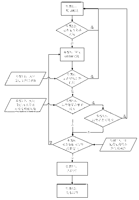
The invention discloses an online optical cable monitoring device, comprising an independent light source, a first optical distribution frame, multiple optical cables to be measured, a second optical distribution frame and multiple wavelength division multiplexing modules, which are arranged in sequence, wherein the wavelength division multiplexing modules are connected with the second optical distribution frame, each wavelength division multiplexing module is respectively connected with an optical power module and an optical switch module, the optical power module is connected with an operation control terminal, the optical switch module is connected with an optical time domain reflector, and the operation control terminal is connected with the optical time domain reflector. The invention also discloses an online optical cable monitoring method for improving the alarm accuracy rate. In the operation control terminal, the following judgments are made in sequence: whether loss data detected by the optical time domain reflector exceeds an alarm threshold or not, whether the alarm position is in a junction or not, whether the loss of the junction is in the acceptable loss range or not, and whether the continuous alarm times of the same optical fiber core of the same optical fiber exceed the continuous alarm times threshold or not. By the adoption of thedevice and the method, the alarm accuracy rate of online optical cable monitoring is effectively improved, and the situations of no alarm, short or instantaneous false alarm caused by artificial operation are reduced.

Description

technical field [0001] The invention relates to an optical cable monitoring device, in particular to an optical cable online monitoring device and a method for improving alarm accuracy. Background technique [0002] In the optical cable loss testing device of the prior art, when monitoring the loss of the optical cable, the loss test is usually performed on all the monitored optical cables within a set period, and the control terminal reads the optical time domain reflectometer (Optical Time Domain Reflectometer, OTDR) Measured loss data, when the loss data exceeds a fixed threshold, an event is recorded and an alarm is issued. The loss monitoring method in the prior art has the following defects: (1) Since the default alarm threshold of the system is only fixed at 1dB, it is prone to false alarms caused by human operation; It is identified as an alarm occurrence, so short-term or instantaneous false alarms are prone to occur; (3) Some original fixed loss points in the OTDR...

Claims


Application Information

Patent Timeline
IPC IPC(8): H04B10/079H04B10/071
Inventor 虞振宇赵甦齐建群周海荣李伟华张春生张喜友吴祖明吴国栋吴佳伟
Owner STATE GRID CORP OF CHINA
Learn More