
Integrated DC power system with one or more fuel cells

a fuel cell and power system technology, applied in the field of electric power systems, can solve the problems of conventional fuel cells generally not possessing the voltage source characteristics suitable, conventional fuel cells generally do not produce dc output voltage over a narrow range to meet, and the output characteristic of conventional fuel cells is typically non-ideal

Inactive Publication Date: 2009-11-12
ELTEK VALERE U S
View PDF1 Cites 13 Cited by
  • Summary
  • Abstract
  • Description
  • Claims
  • Application Information

AI Technical Summary

Benefits of technology

[0015]For a more complete understanding of the present invention and the advantages thereof, reference is now made to the following Detailed Description taken in conjunction with the accompanying drawings, in whi...

Problems solved by technology

However, conventional fuel cells generally do not produce a DC output voltage over a narrow enough range to comply with most general power system DC voltage bus specifications.
Additionally, conventional fuel cells generally do not possess the required voltage source characteristics suitable for direct connection to a DC voltage bus.
Because the output characteristic of conventional fuel cells is typically non-ideal, conventional fuel cells require energy conversion to couple their energy to a DC voltage bus.
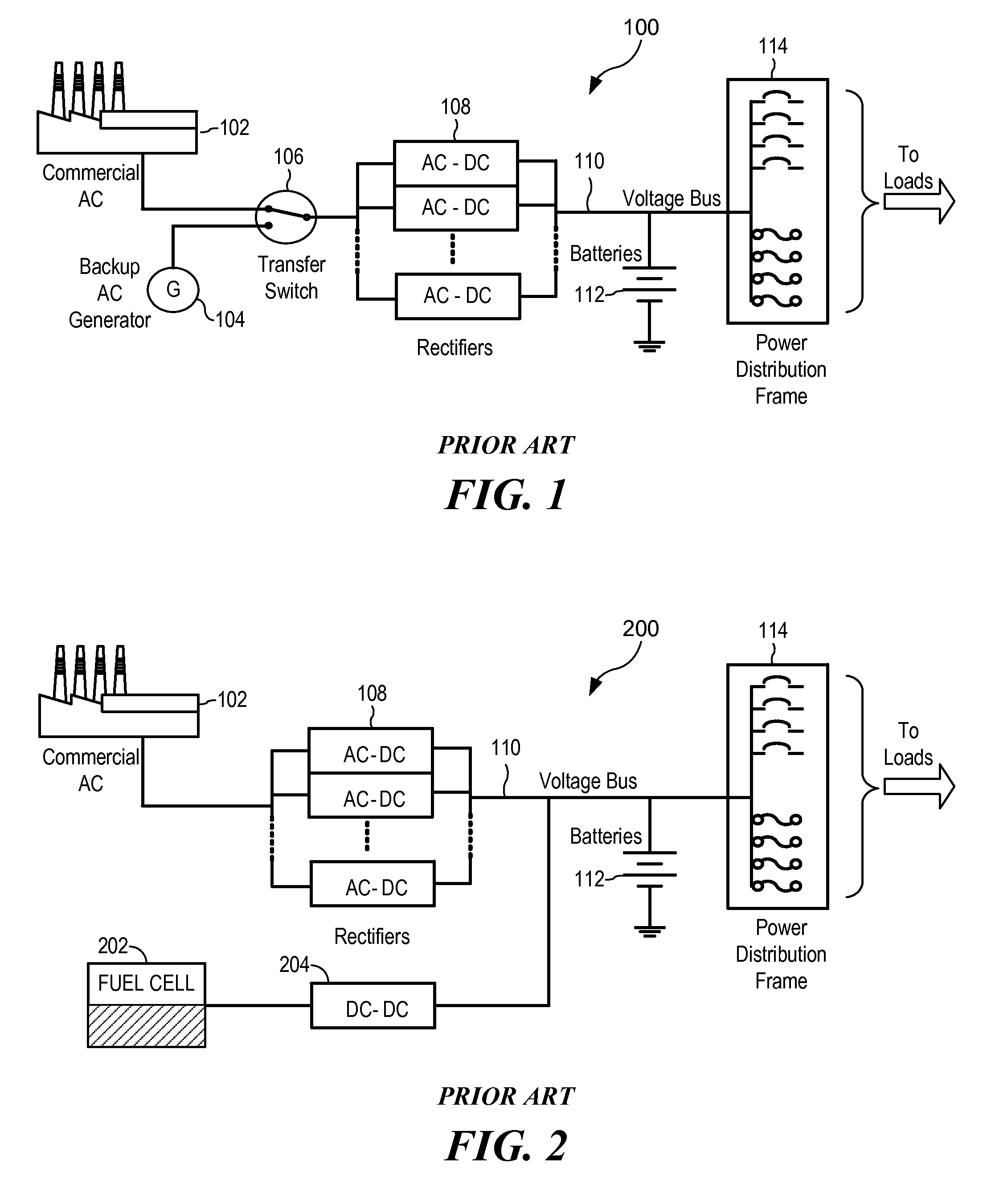
The use of a DC-DC converter such as DC-DC converter 204 in a power system such as power system 200 may cause several problems.
First, a DC-DC converter may add cost to the power system.
Second, the DC-DC converter may reduce the efficiency of the power system and increase power loss.
Third, the DC-DC converter may add weight and increase the size of the overall solution.
Fourth, the additional losses of the DC-DC converter may require the storage of extra fuel, such as hydrogen, used by the fuel cell to produce power.
The extra cooling may increase the size, initial costs, operating costs, and energy usage of the overall solution.
Readily available off-the-shelf DC-DC converters may not be suitable for various power system applications, thereby complicating the commercial availability of such devices.

Method used


Image

  • Integrated DC power system with one or more fuel cells
  • Integrated DC power system with one or more fuel cells
  • Integrated DC power system with one or more fuel cells

Examples


Embodiment Construction

[0020]In the following discussion, numerous specific details are set forth to provide a thorough understanding of the present invention. However, those skilled in the art will appreciate that the present invention may be practiced without such specific details. In other instances, well-known elements have been illustrated in schematic or block diagram form in order not to obscure the present invention in unnecessary detail. Additionally, for the most part, specific details, and the like have been omitted inasmuch as such details are not considered necessary to obtain a complete understanding of the present invention, and are considered to be within the understanding of persons of ordinary skill in the relevant art.

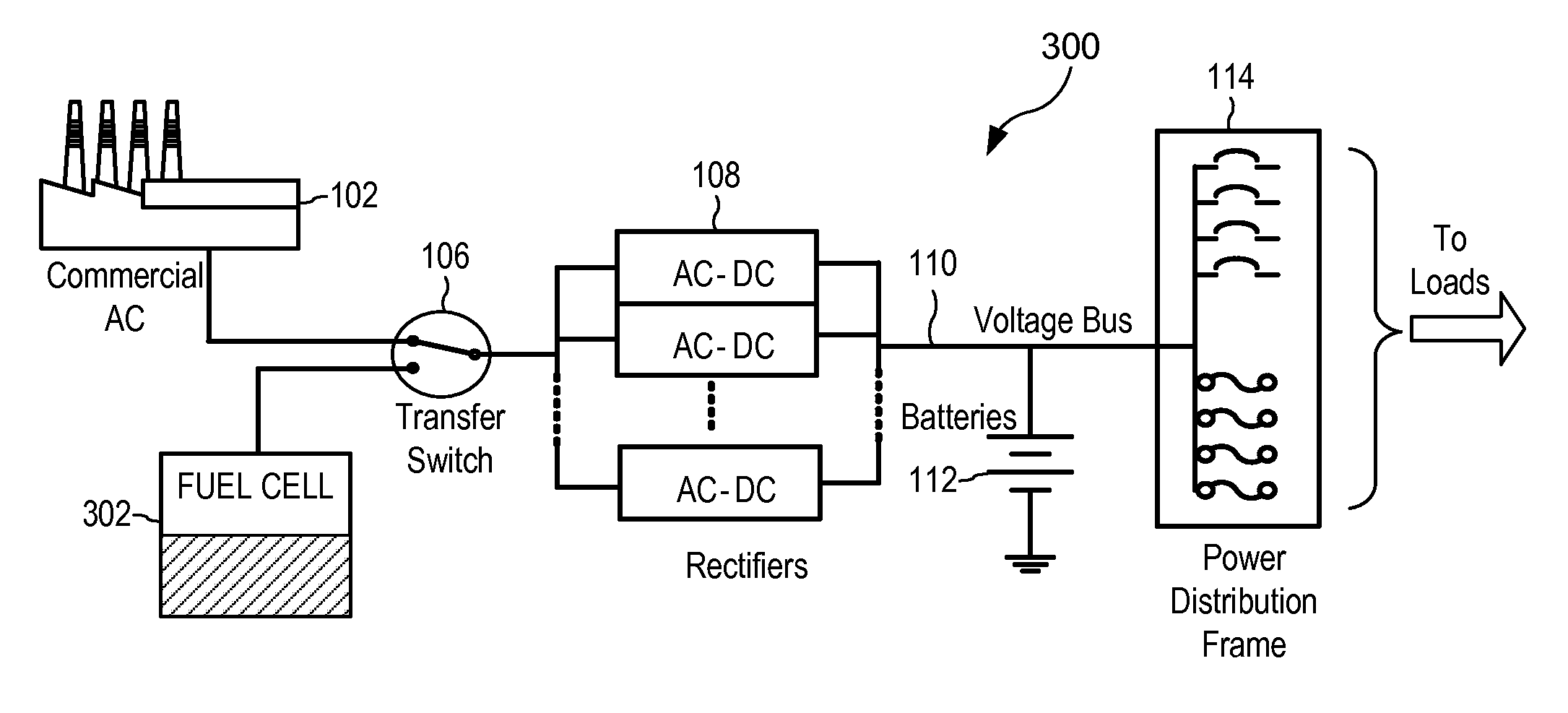
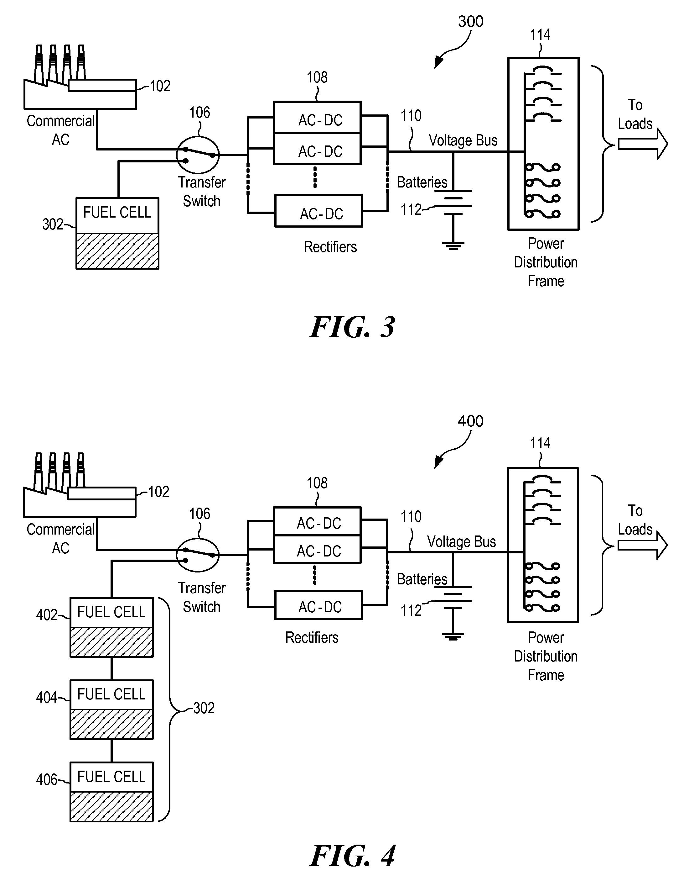
[0021]Referring to FIG. 3, power system 300 is a power system in accordance with an exemplary embodiment of the present invention. Power system 300 includes commercial AC power source 102, transfer switch 106, AC-DC rectifiers 108, voltage bus 110, batteries 112, and power...


PUM


Abstract

A power system has at least an AC power source, a DC power source, a transfer switch, at least one AC-DC rectifier, and a power distribution frame. The transfer switch is coupled to the AC power source and the DC power source. The at least one AC-DC rectifier is coupled to the transfer switch and has a boost regulator. A power distribution frame is coupled to the AC-DC rectifier.A method of switching from an AC power source to a DC power source includes at least isolating the AC source from an input of at least one AC-DC rectifier, connecting the DC source to the input, and sending a signal to a boost regulator of the rectifier to switch from power factor correction operation to fuel cell operation. In fuel cell operation the output of the DC source is matched by the boost regulator.

Description

CROSS-REFERENCE TO RELATED APPLICATIONS[0001]This application relates to, and claims the benefit of the filing date of, co-pending U.S. provisional patent application Ser. No. 61 / 050,756 entitled INTEGRATED DC POWER SYSTEM WITH ONE OR MORE FUEL CELLS, filed May 6, 2008, the entire contents of which are incorporated herein by reference for all purposes.TECHNICAL FIELD[0002]The present invention relates to electric power systems and, more particularly, to electric power systems having one or more DC electric power sources.BACKGROUND[0003]Generally, power and battery plants, or other related power systems, utilize a common voltage bus to provide seamless, uninterrupted power during periods of commercial AC outage. Referring to FIG. 1, power system 100 is an example of a conventional power system using AC generator back-up. Power system 100 may include commercial AC power source 102, back-up AC generator 104, transfer switch 106, AC-DC rectifiers 108, voltage bus 110, batteries 112, and...

Claims


Application Information

Patent Timeline
IPC IPC(8): H02J1/00
CPCH02J1/102Y02B90/14H02J2001/004H02J9/061H02J2300/30Y02B90/10Y02P80/10
Inventor CIOFFI, ALFONSO J.
Owner ELTEK VALERE U S
Learn More