Loadshedding uninterruptible power supply

a power supply and load-shedding technology, applied in emergency power supply arrangements, liquid/fluent solid measurement, instruments, etc., can solve the problems of disruption of electrical power sources, loss of human life, and disruption of power transmission to the ultimate end point of use, so as to eliminate the expense

Inactive Publication Date: 2005-02-08
HEWLETT-PACKARD ENTERPRISE DEV LP
View PDF8 Cites 32 Cited by
  • Summary
  • Abstract
  • Description
  • Claims
  • Application Information

AI Technical Summary

Benefits of technology

The present invention overcomes the problems that are outlined above by providing a UPS and associated methodology for managing a dual power supply system in a manner that prevents the UPS from becoming a single point of failure. These improvements eliminate the expense of providing duplicate UPS devices in dual power systems that are designed to avoid single points of failure.

Problems solved by technology

Frequently, the transmission of power to the ultimate end point of use is disrupted, e.g., by a rolling blackout or weather conditions that damage the power transmission lines.
Disruption of electrical power sources cannot be tolerated in situations where a continuous power source is necessary for the operation of critical electronic devices or where the disruption is likely to cause harm.
For example, disruption of power to a telecommunications server for use in emergency medical situations might result in the loss of human life.
Many businesses are unable to function without their computer systems in an operational state.
Critical data may be irretrievably lost due to an abrupt power failure.
The use of a dedicated UPS on a single power line does not necessarily prevent system shutdown.
This dual deployment is duplicative and thus, expensive.
Failure of either power supply or either UPS can induce a shutdown of an attached electrical device when one of the UPS devices diagnoses a power failure condition, even though the other power supply or UPS may be intact and operational.
A major problem with having a single UPS connected to two power sources is that the UPS is a single point of failure.
It remains a problem to implement a single UPS to manage a dual power supply system in a manner that prevents the UPS from becoming a single point of failure.

Method used


Image

  • Loadshedding uninterruptible power supply
  • Loadshedding uninterruptible power supply
  • Loadshedding uninterruptible power supply

Examples


Embodiment Construction

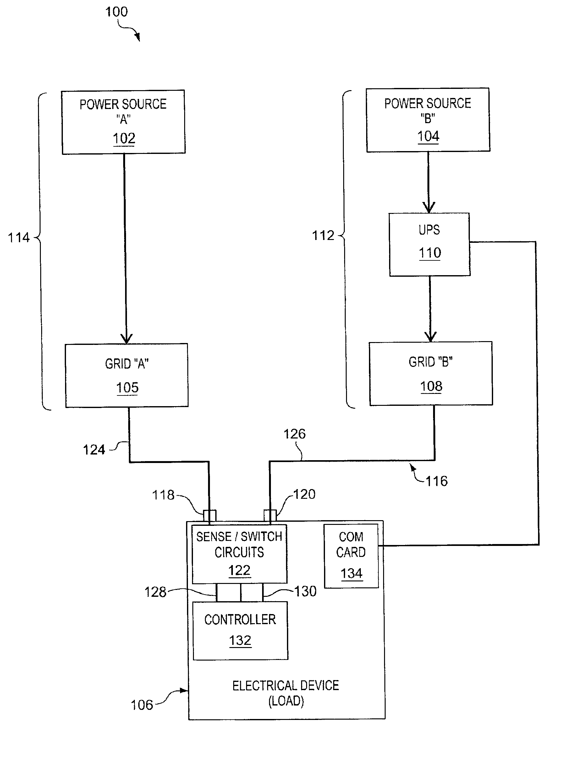
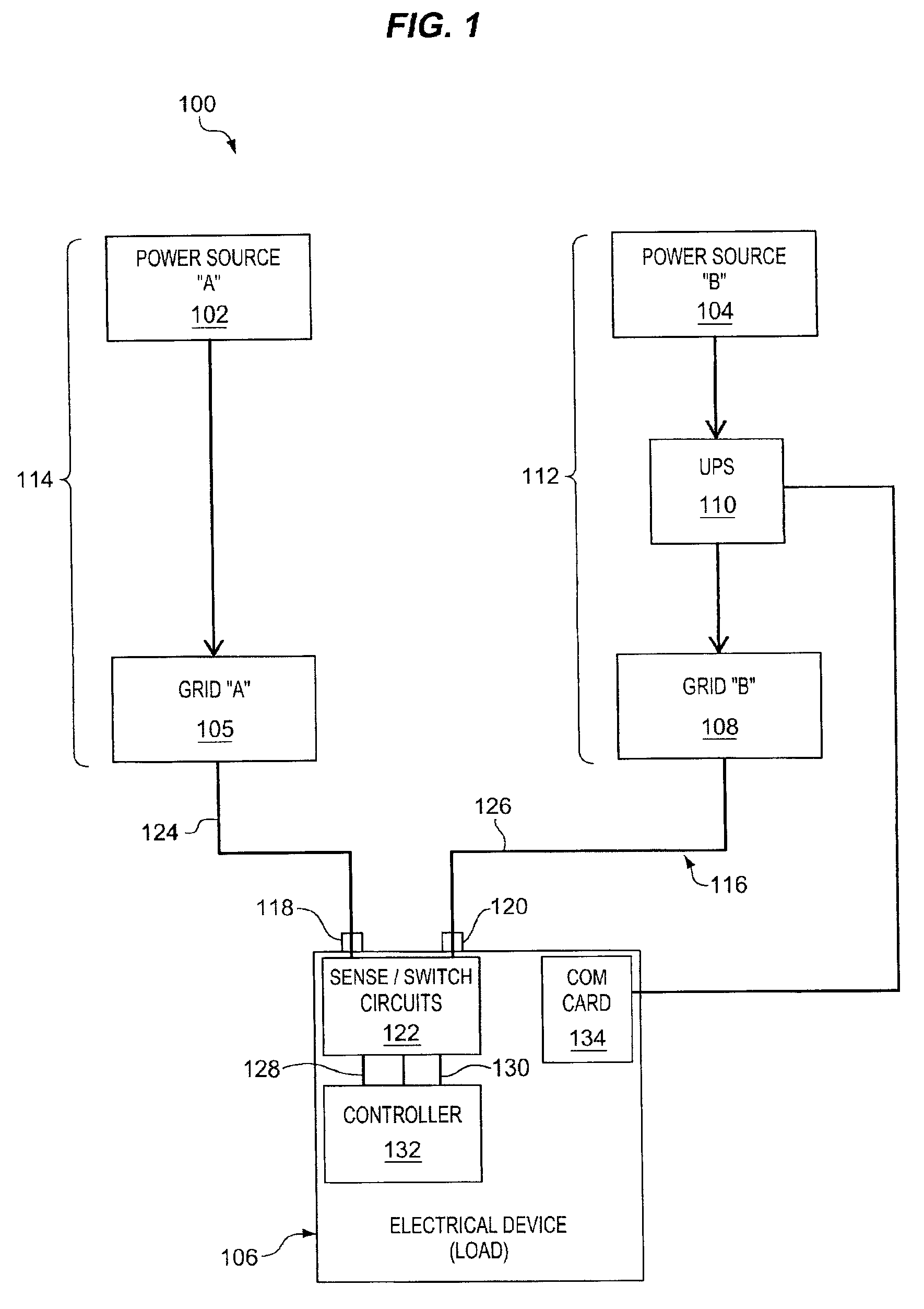
FIG. 1 shows a block diagram of a dual power source system 100. A first power source 102, which is also designated as power source “A,” may be any power source, but is preferably a primary power source, such as a power transmission line that carries power originating from a power generation company. A second power source 104 may also be any power source, but is preferably a backup power source, such as an auxiliary generator or alternator system. Other types of power sources that may be used as the first or second power sources 102 and 104 include, for example, solar panels, wind charging systems, batteries, and fuel cells. Either the first power source 102 or the second power source 104 is alone capable of providing sufficient power to operate an electrical device 106, which may be any electrical device in any multiple power source system. Categories of electrical device 106 include, by way of example, telecommunications servers, computer networks, network servers, computational de...


PUM


Abstract

A dual power source system includes a first power source and a second power source operably coupled with an electrical device, as well as a switching mechanism capable of selecting between the first and second power sources. An uninterruptible power supply (UPS) is place in line with one of the first and second power sources leading to the electrical device. Sense circuitry is capable of identifying a power failure condition in either the first or second power sources. A controller utilizes signals from the sense circuitry to selectively switch between the first and second power sources while configuring the UPS in a manner of providing for a plurality of operational states that accommodate the electrical device with operational power despite any combination of power failures in the first and second power sources.

Description

BACKGROUND OF THE INVENTION1. Field of the InventionThe invention pertains to the field of uninterruptible power supplies (UPS) for use in providing continuous power to electrical devices in the event of a primary power system failure. More specifically, the UPS is adapted for use in systems having two primary sources of power in addition to the UPS.2. Discussion of the Related ArtUPS devices are useful in preventing unwanted failure in electrical devices due to failure of an incoming power source. For example, a power utility company for a state or municipality may have a large industrial facility for converting energy from fossil fuels into electrical power. The resultant electricity travels on power transmission lines until the electricity arrives at an ultimate point of use. Frequently, the transmission of power to the ultimate end point of use is disrupted, e.g., by a rolling blackout or weather conditions that damage the power transmission lines.Disruption of electrical power ...

Claims


Application Information

Patent Timeline
Patent Type & Authority Patents(United States)
IPC IPC(8): G06F1/26G06F1/30H02J9/06
CPCG06F1/30G06F1/263
Inventor SMITH, ROBERT B.WINICK, BRADLEY D.CROSS, EDWARD A
Owner HEWLETT-PACKARD ENTERPRISE DEV LP
Why Eureka
Try Eureka