One cycle PFC boost converter IC with inrush limiting, fan control and housekeeping supply control

A boost converter, single-cycle control technology, applied in high-efficiency power electronic conversion, control/regulation systems, instruments, etc., can solve the problems of high discrete components, complex design, difficulties, etc., and achieve the effect of eliminating the need

Inactive Publication Date: 2007-10-03
INTERNATIONAL RECTIFIER COEP
View PDF5 Cites 11 Cited by
  • Summary
  • Abstract
  • Description
  • Claims
  • Application Information

AI Technical Summary

Problems solved by technology

[0005] The above prior art with multiplier solutions has the disadvantage of high discrete component count and complex design and requires development work to realize high performance continuous conduction mode power facto

Method used


Image

  • One cycle PFC boost converter IC with inrush limiting, fan control and housekeeping supply control
  • One cycle PFC boost converter IC with inrush limiting, fan control and housekeeping supply control
  • One cycle PFC boost converter IC with inrush limiting, fan control and housekeeping supply control

Examples


Embodiment Construction

[0043] DETAILED DESCRIPTION OF THE PREFERRED EMBODIMENT

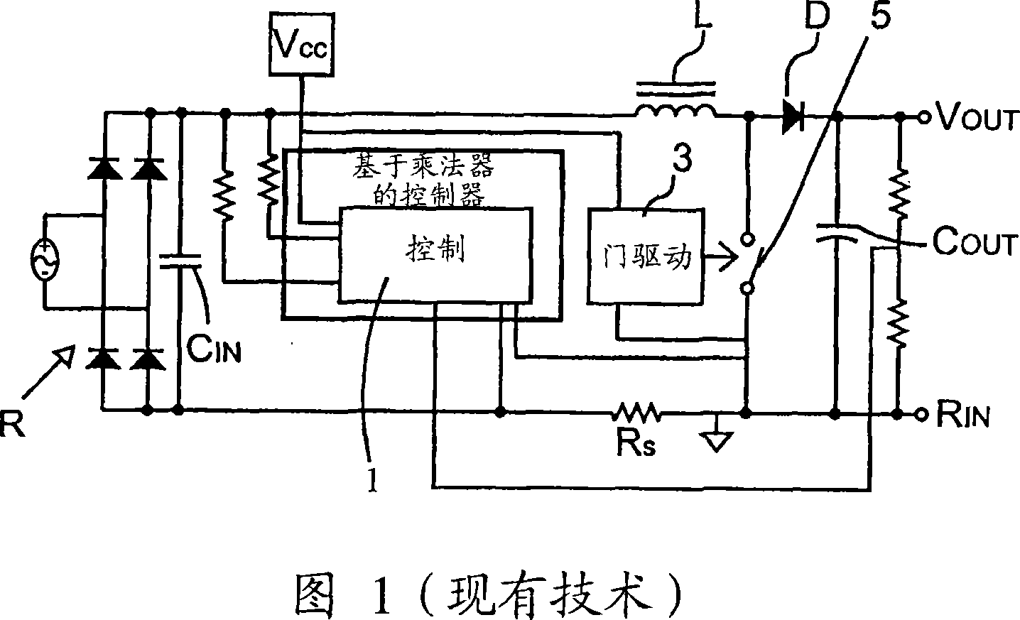
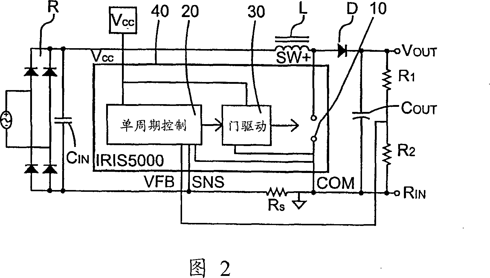
[0044] Figure 2 depicts a system-level block diagram representation of an OCC-based active power factor correction technique operating under a fixed-frequency, continuous conduction-mode boost converter topology. In CCM, the current in the inductor L is never allowed to go to zero. In the circuit of Fig. 2, the power switch 10, the PFC control circuit 20 based on OCC and the built-in (onboard) power switch driving circuit 30 are integrated into a single package 40, and the package 40 can dissipate the appropriate heat from the device to radiator (heatsink). Various power packages can be realized with this technique because the use of OCC technique reduces the number of pins required to implement a full CCM PFC boost converter.

[0045] The control circuit 20 is based on the OCC method in which the multipliers and input voltage sensing described with reference to the prior art circuit in FIG. 1 are not required. This ...


PUM


Abstract

A power factor corrected boost converter circuit comprising a rectifier connectable to an ac input and having a rectified dc output provided across a dc bus, an inductor having first and second terminals connected in one leg of the dc bus, a first terminal of the inductor coupled to the output of said rectifier, an integrated circuit comprising a control circuit for controlling a switch, the integrated circuit comprising a housing enclosing the control circuit, the integrated circuit having a power terminal, a ground terminal, a first control input terminal coupled to an output of the converter circuit, and a second control input terminal coupled to a sensor for sensing current in the dc bus and further having an output terminal connected to the switch, a boost rectifier diode having a first terminal, the first terminal of the diode coupled to the second terminal of the inductor, the diode having a second terminal, and a storage capacitor connected to the second terminal of the diode, wherein the control circuit comprises a one cycle control circuit having an integrator reset by a clock signal for each cycle of the clock signal, the integrator receiving as an input a signal provided on said first control input terminal, further comprising an inrush current limiting circuit for limiting the current through the inductor to a value below a predetermined level. Also disclosed is a fan motor speed controller and a housekeeping power supply controller.

Description

[0001] Cross References to Related Applications [0002] This application is based on and claims the patent application entitled "Single-Cycle Controlled Continuous Conduction Mode PFC Boost Converter IC with Inrush Current Limiting and Fan Speed ​​Control" filed November 1, 2002 by Frank Athari U.S. Provisional Application No. 60 / 423,191 and filed December 9, 2002 by Frank Atari entitled "Continuous Conduction Mode PFC Boost Converter IC with Integrated Inrush Current Limiting, Fan Speed, and Internal Regulatory Control priority of U.S. Provisional Application No. 60 / 431,858. The disclosures of the aforementioned applications are incorporated herein by reference. Background of the invention [0003] One Cycle Control (OCC) techniques for controlling switching circuits are now well known. Its general technique is described in US Patent No. 5,278,490. This technique is applied to a PFC (Power Factor Correction) boost converter in US Patent No. 5,886,586. In OCC technique, w...

Claims


Application Information

Patent Timeline
IPC IPC(8): G05F1/10
CPCY02B70/126
Inventor 弗兰克・阿塔瑞
Owner INTERNATIONAL RECTIFIER COEP
Why Eureka
Try Eureka