Fuel feed apparatus having vibration damping structure

a technology of vibration damping structure and fuel feed, which is applied in the direction of marine propulsion, vessel construction, separation processes, etc., can solve the problem that the vibration of the fuel pump is not apt to be transmitted to the sub-tank, and achieve the effect of preventing eccentric vibration and easy manufacturing of the supporting member

Active Publication Date: 2005-02-15
DENSO CORP
View PDF10 Cites 22 Cited by
  • Summary
  • Abstract
  • Description
  • Claims
  • Application Information

AI Technical Summary

Benefits of technology

In the present invention, a casing is connected with the sub tank via a supporting member. The casing accommodates the pump. The casing contacts the sub tank via a suction filter. The supporting member has resiliency, so as to absorb vibration of the fuel pump. Therefore, vibration of the fuel pump is not apt to be transmitted to the sub tank via the supporting member. The suction port of the fuel pump does not directly contact sub tank, so that vibration of the fuel pump is less transmitted from the suction port to the sub tank.
Furthermore, the casing is supported by the sub tank via the supporting member and the suction filter. Namely, the casing is supported by not only the supporting member. Therefore, the supporting member need not be highly rigid. That is, the supporting member can be resilient. Thus, manufacturing of the supporting member becomes easy. Besides, the supporting member is connected with the sub tank at multiple points, so that eccentric vibration can be prevented. As described in following embodiment, the supporting member can directly connect with the fuel pump, so that the resilient supporting member can connect the fuel pump and the sub tank, or the resilient supporting member can connect the fuel pump and the fuel tank, for example.

Problems solved by technology

Therefore, vibration of the fuel pump is not apt to be transmitted to the sub tank via the supporting member.

Method used


Image

  • Fuel feed apparatus having vibration damping structure
  • Fuel feed apparatus having vibration damping structure
  • Fuel feed apparatus having vibration damping structure

Examples


first embodiment

(First Embodiment)

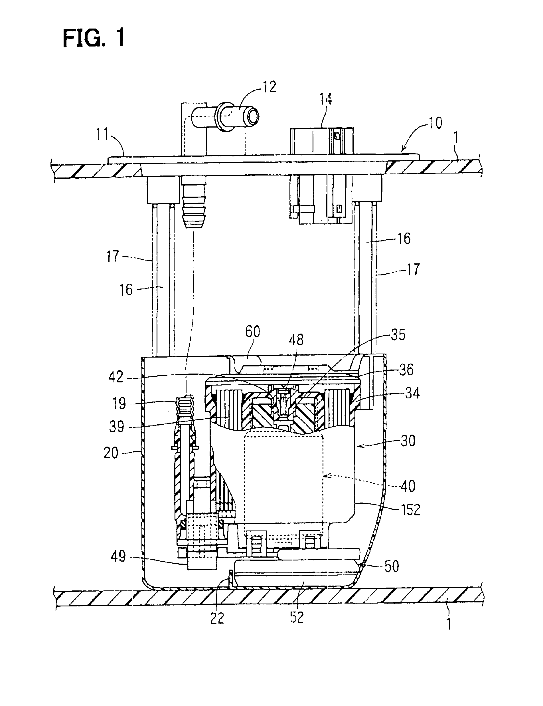
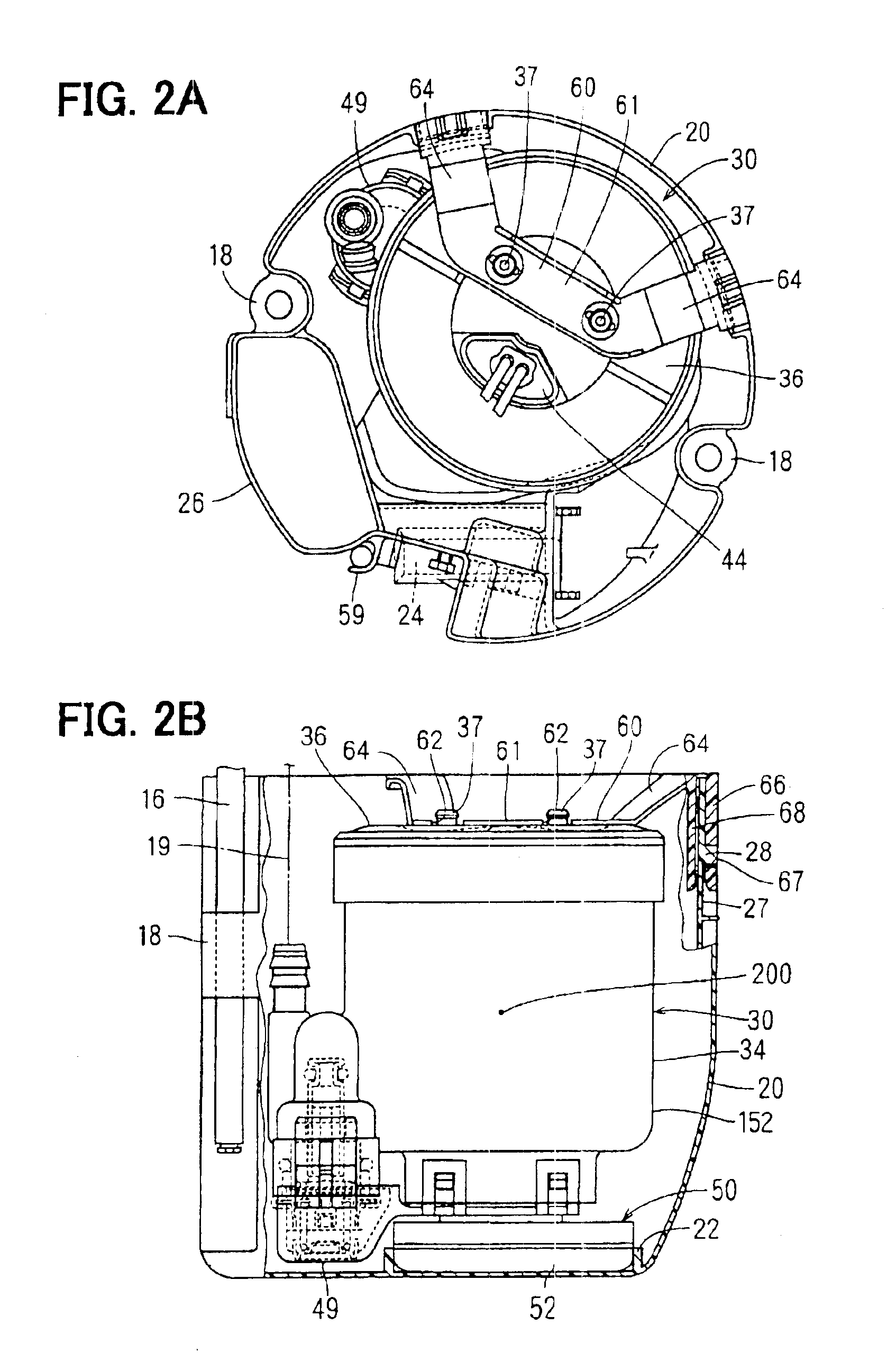
As shown in FIG. 1, a lid 11 of a fuel feed apparatus 10 is formed in a disc-shape and mounted on the top wall of a resinous fuel tank 1. The fuel tank 1 can be made of a metallic material. Other members of the fuel feed apparatus 10 are accommodated in the fuel tank 1. The fuel tank 1 has a tank section. A jet pump can transfer fuel from the tank section toward another tank section which includes a pump module 30 inside the fuel feed apparatus 10.

A discharge pipe 12 and an electric connector 14 are built on the lid 11. Fuel is discharged from a fuel pump 40 of the pump module 30 toward outside of the fuel tank 1 through the discharge pipe 12. The connector 14 supplies the fuel pump 40 with electric power via lead wires. A metallic pipe 16 is press-inserted into the lid 11 at its one end, and loosely inserted into an insertion section 18 at the other end (FIGS. 2A and 2B). The insertion section 18 is formed in a sub tank 20. A spring 17 presses the lid 11 and the s...

second embodiment

(Second Embodiment)

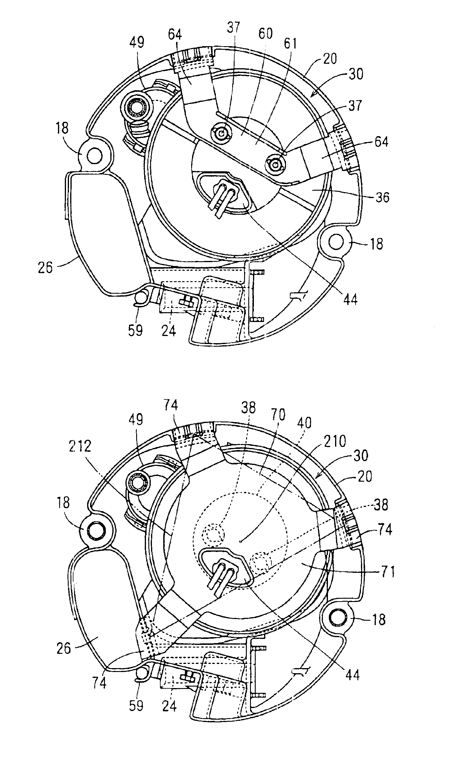
As shown in FIG. 4, a supporting member 70 connects the lid 36 of the casing 34 and the sub tank 20. The supporting member 70 is made of a resilient thin plate. The supporting member 70 has a central section 71 and three arm sections 74. The central section 71 snap-fits to the lid 36, and the three arm sections 74 snap-fit to the peripheral wall 27 of the sub tank 20. Protrusions 72 are formed on the central section 71 toward the lid 36. Fitting holes 36 are formed on the top surface of the lid 36. The protrusions 72 snap-fit to the fitting holes 38 at two places, so that the central section 71 is connected with the lid 36. Each arm section 74 of the supporting member 70 has an outer peripheral section 76 and an inner peripheral section 78, for clipping the peripheral wall 27 in the diametrical direction of the sub tank 20. A window 77 is formed in each outer peripheral sec-ion 76 so as to hook each corrsponding claw 28 which protrudes from the peripheral wall 27 ...

third embodiment

(Third Embodiment)

As shown in FIG. 5, Three supporting members 90 are formed individually. The three supporting members 90 are arranged in a constant interval in the peripheral direction of the pump module 30, and connect the bottom section of the casing 34 and the sub tank 20. The central axis 210 of the pump module 30 is positioned in the triangular area 212, which is formed by connecting the three points where the three supporting members 90 snap-fit to the pump module 30 and the sub tank 20. The supporting members 90 are made of a resilient thin plate. Each supporting member 90 has a connecting section 91, a first arm section 92 and a second arm section 94. The first arm section 92 snap-fits to each corresponding protrusion 100 formed on the bottom section of the casing 34. The second arm section 94 is connected with the first arm section 92 via the connecting section 91 so as to snap-fit to the peripheral wall 27 of the sub tank 20. The protrusion 100 snap-fits to a fitting hol...


PUM

PropertyMeasurementUnit
resiliencyaaaaaaaaaa
gravityaaaaaaaaaa
inner diameteraaaaaaaaaa

Abstract

A fuel feed apparatus accommodates a sub tank. The sub tank includes a pump module The pump module generates vibration, and is supported by a supporting member and a suction filter. The suction filter is covered with a nonwoven fabric. The nonwoven fabric is used as an additional filter for removing debris in fuel drawn by the pump module. The supporting member and the nonwoven fabric have resilience. The pump module is mounted on the sub tank via the supporting member and the non woven fabric. Therefore, vibration of the pump module is not apt to be transmitted to the sub tank. Additionally, the supporting member need not to be rigidly formed, so that the supporting member can be manufactured easily.

Description

CROSS REFERENCE TO RELATED APPLICATIONThis application is based on Japanese Patent Applications No. 2002-345660 filed on Nov. 28, 2002 and No. 2003-351897 filed on Oct. 10, 2003, the disclosure of which is incorporated herein by reference.BACKGROUND OF THE INVENTIONThe present invention relates to a fuel feed apparatus, that includes a fuel pump provided in a fuel tank.Conventionally, an in-tank type fuel feed apparatus is used for drawing fuel in a fuel tank and discharging the fuel. Here, a fuel pump is disposed in the fuel feed apparatus, which is in the fuel tank. According to JP-A-9-268956 (U.S. Pat. No. 5,769,051), a pump module is accommodated in a sub tank. The pump module includes a fuel filter surrounding the periphery of the fuel pump and the fuel pump. According to U.S. Pat. No. 5,038,741, a pump is accommodated in a canister. The pump directly draws fuel in the fuel tank through the filter which protrudes from the bottom area of the canister to the outside of the canist...

Claims


Application Information

Patent Timeline
Patent Type & Authority Patents(United States)
IPC IPC(8): F02M37/10F02M37/08F02M37/00F02M37/22
CPCF02M37/106
Inventor EBIHARA, YOSHIONAGATA, KIYOSHIYAMADA, KATSUHISAIZATANI, KOUJISAKAI, TATSUOUMETSU, KUNIHIRO
Owner DENSO CORP
Why Eureka
Try Eureka