Connector fixing structure

a technology for fixing structures and connectors, applied in the direction of coupling device connections, transportation and packaging, engagement/disengagement of coupling parts, etc., can solve the problems of limited mounting space, reduced shielded connectors, and short cable lengths

Inactive Publication Date: 2007-05-31
TOYOTA JIDOSHA KK +4
View PDF3 Cites 19 Cited by
  • Summary
  • Abstract
  • Description
  • Claims
  • Application Information

AI Technical Summary

Benefits of technology

[0025] According to the present invention, a fixed state of the cable established by the second fixing member (e.g. a clamp) is such a state as to allow for more movement of the shielding portion than does a fixed state of the shielding portion established by the ...

Problems solved by technology

Since the fiat plate portion can be bent with a bending radius smaller than that of the shielded electrical wire, the bent portion thereof can be made smaller, resulting in downsizing of the entire shielded connector.
However, if a rotating electrical machine is mounted on an HV vehicle of a Front engine Rear drive (FR) type, for example, the rotating electrical machine is required to be mount...

Method used


Image

  • Connector fixing structure
  • Connector fixing structure
  • Connector fixing structure

Examples


first embodiment

[0032] A connector according to the present embodiment is composed of a male connector and a female connector. The male connector and the female connector have a contact point and a contact therein, respectively, which correspond to each other. By fitting the male connector into the female connector, their contact point and contact are joined together and electrically connected. The female connector composing the connector according to the present embodiment is provided at a housing of a rotating electrical machine. The male connector to be fitted into the female connector is fixed to the housing in a plurality of positions.

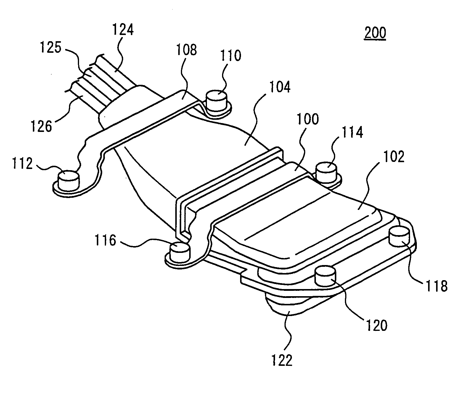
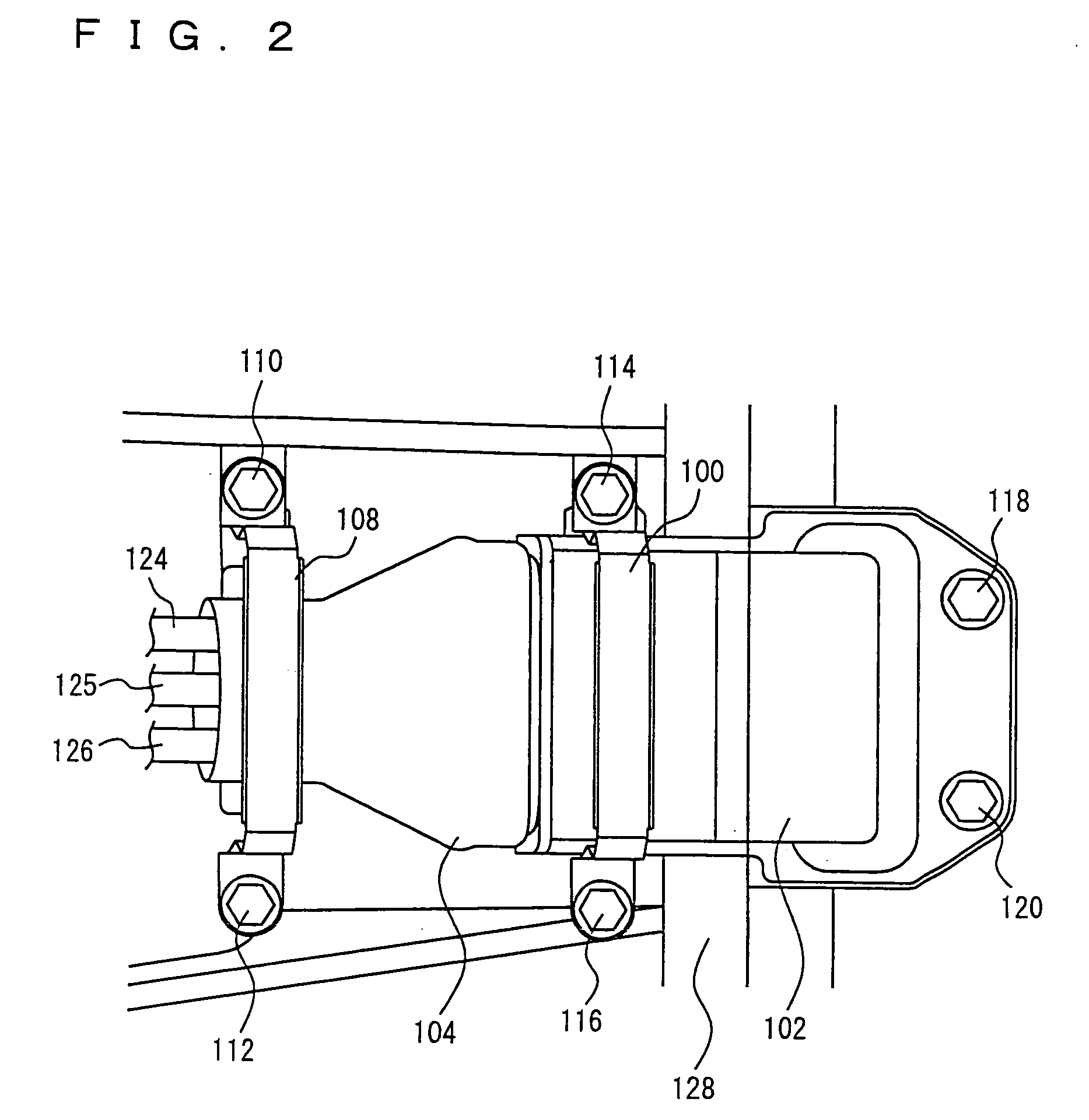
[0033] As shown in FIG. 1, a male connector 200 composing a connector according to the present embodiment is composed of a shield shell 102, clamps 100 and 108, bolts 110-120, a cable cover 104, cables 124, 125 and 126, and a connector portion 122.

[0034] Each of cables 124, 125 and 126 corresponds to each of the phases of a three-phase alternating current motor...

second embodiment

[0048] A connector fixing structure according to a second embodiment will now be described with reference to FIG. 5. A male connector 200 composing a connector according to the second embodiment includes a clamp 142 instead of clamps 100 and 108 at male connector 200 according to the first embodiment described above. Other structures are the same as those of the first embodiment. Therefore, the detailed description thereof will not be repeated here.

[0049] Clamp 142 is integrally formed with shield shell 102 by being fixed thereto by caulking or the like. Clamp 142 is a plate-like metal plate with four end portions. The four end portions are fixed to housing 128 with bolts 110-116, respectively.

[0050] Each of portions from the plate-like metal plate to the four end portions is formed into a shape exhibiting elasticity. Clamp 142 may further be fixed to cable cover 104 by caulking or the like.

[0051] As described above, a connector fixing structure according to the present embodimen...


PUM


Abstract

A male connector to be connected to a female connector provided at a housing accommodating a vehicle-mounted electrical device includes a contact point to be connected to a contact of the female connector, a cable connected to the contact point, and a shield shell covering the contact point. A fixing structure for the male connector includes a bolt for fixing the shield shell to the housing, on the contact point side, and a clamp for fixing the cable to the housing, on the cable side. The fixed state of the cable established by the clamp is such a state as to allow for more movement of an object to be fixed than does the fixed state of the shield shell established by the bolt.

Description

TECHNICAL FIELD [0001] The present invention relates to a connector fixing structure, and more particularly, to a fixing structure absorbing vibrations in a cable. BACKGROUND ART [0002] Conventionally, a vehicle such as a Hybrid Vehicle (HV), an Electric Vehicle (EV), or a Fuel Cell Vehicle (FCV) has a plurality of electrical devices mounted thereon. In a vehicle having a rotating electrical machine mounted thereon, for example, electrical devices such as the rotating electrical machine and an inverter are connected to each other via a cable such as a lead wire. At this time, when a cable such as a lead wire is connected to an electrical device, a connector is usually used. In other words, a cable and an electrical device are respectively provided with connectors shaped to be fittable with respect to each other. Each of the connectors serves as a male connector or a female connector and has a contact point for making electrical connection. Therefore, by fitting a male connector into...

Claims


Application Information

Patent Timeline
IPC IPC(8): H01R9/03B60R16/02H01R13/46H01R13/533H01R13/595H01R13/62H01R13/73H02G3/38
CPCH01R13/595H01R13/73
Inventor TSUKASHIMA, HIROYUKITAKEUCHI, TAKAMASAKONDA, KAZUMOTOMIYAZAKI, SHO
Owner TOYOTA JIDOSHA KK
Why Eureka
Try Eureka