Floating platform and energy producing plant comprising such a floating platform

a technology of floating platforms and energy producing plants, which is applied in the direction of floating buildings, motors, anchoring arrangements, etc., can solve the problems of unsuitable placement, uneconomical placement further out to sea, and practical economic problems of supervision and maintenan

Inactive Publication Date: 2015-09-17
HEXICON
View PDF4 Cites 10 Cited by
  • Summary
  • Abstract
  • Description
  • Claims
  • Application Information

AI Technical Summary

Benefits of technology

[0034]Using the inventive platform as a base for an energy producing plant is particularly of interest since the platform is very well suited for this application, due to the fact that it can operate independent of depth and far out on the open ocean. The platform can be firmly anchored at the bottom by the anchoring system. Preferably the anchoring system is attached to the central unit, thus enabling the entire platform to rotate and automatically adjust in line with the wind and / or water current direction so that the energy producing systems are placed in an optimum position for energy extraction. When wind power generators are used they can be placed on the semi-submersible nodes of the platform, thus enabling access to the generator housing through the hollow interior of the nodes and the connection members.

Problems solved by technology

This placement is not desirable from an environmental view.
To build wind power plants further out to sea meets the problem of a usual greater depth, but also the practical economical problem of supervision and maintenance.
Due to the fact that wind power plants up to today uses separate wind generator units, a placement further out to sea quickly becomes uneconomical.
However, an energy producing plant placed out on the ocean is exposed to hard wind and harsh weather.
When the floating platform is exposed to the power of nature, all components are exposed to large forces which may result in large stress on the components, especially in the connection between the beams and nodes.
Thus, the size and price of the components and the entire platform increases.
However, the vertical forces from the waves are still risking damaging this attachment.
However, these tensioning parts are not possible to adjust in any way.

Method used


Image

  • Floating platform and energy producing plant comprising such a floating platform
  • Floating platform and energy producing plant comprising such a floating platform
  • Floating platform and energy producing plant comprising such a floating platform

Examples


first embodiment

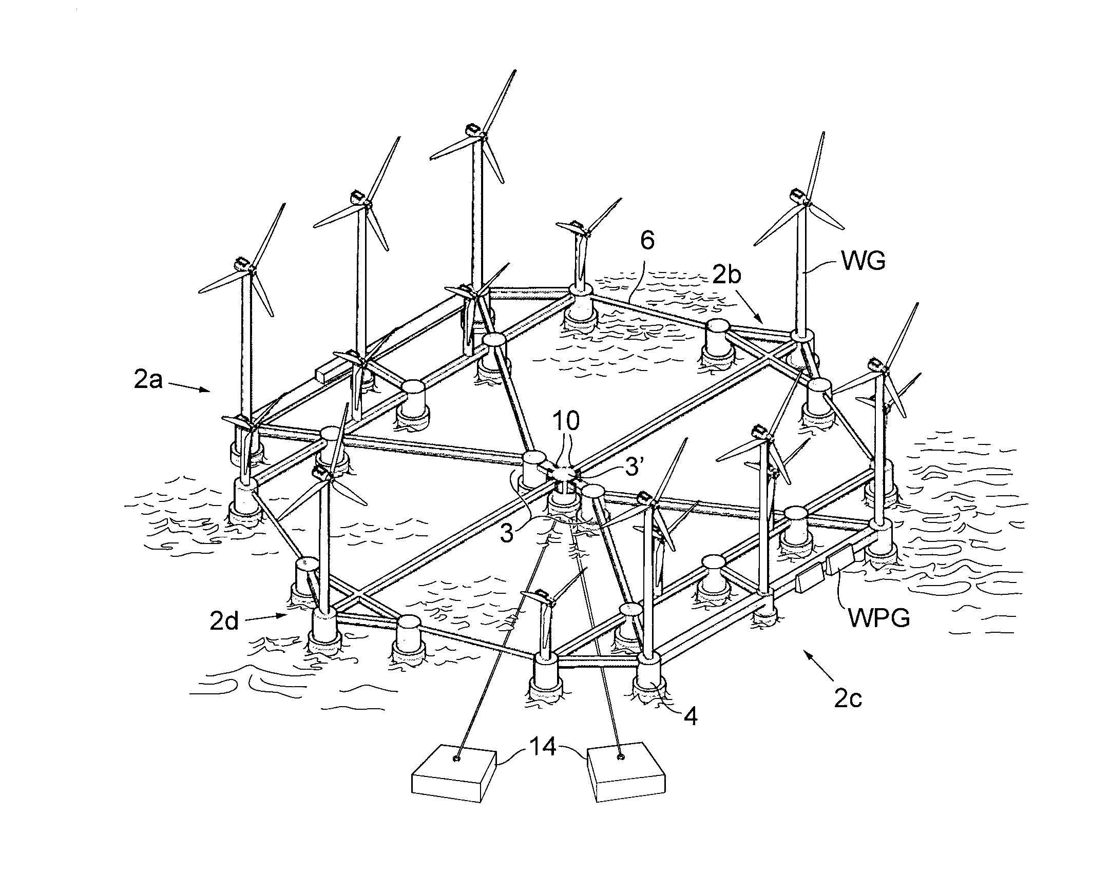
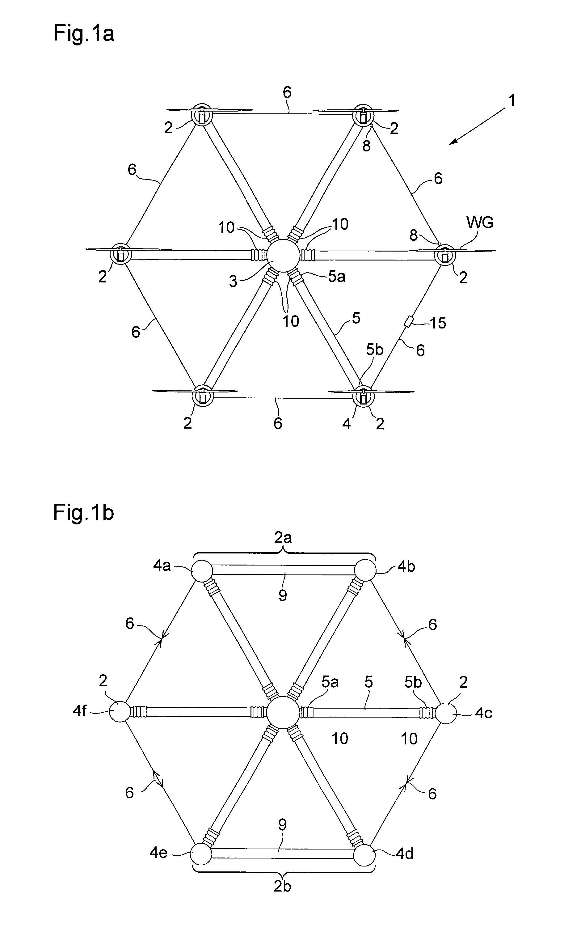
[0043]One first embodiment of the floating platform used as an energy producing plant is disclosed in FIG. 1a. FIG. 1a discloses a floating platform 1 comprising six floating or semi-submersible peripheral units 2 arranged detachably connected to a central floating or semi-submersible unit 3. Each floating peripheral unit 2 is in this embodiment a semi-submersible node 4 on which a wind power generator WG is mounted. However, it is also possible to arrange other types of energy converting systems on the platform.

[0044]Between the peripheral units 2 and the central unit 3 an elongated, rigid radial connection member 5 is arranged protruding in a substantially radial direction from the central unit 3. The connection between the peripheral and central units 2, 3 and the connection members 5, may be detachable by a connection coupling 10 or rigid, i.e. the connections member can be welded or in any other way firmly attached to the peripheral and / or central units 2, 3.

[0045]In the embodi...

second embodiment

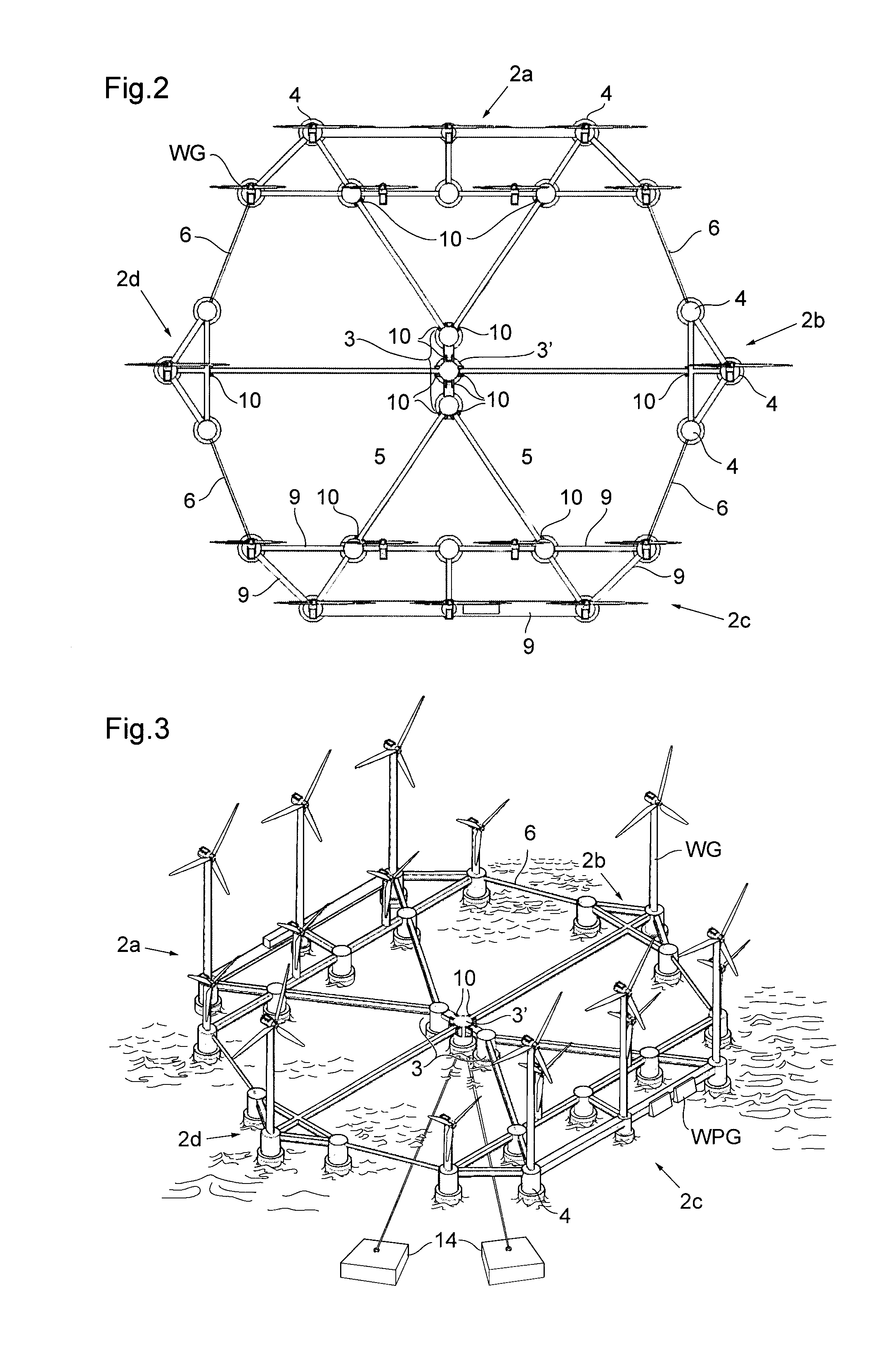
[0049]FIG. 1b discloses the invention. Here at least two of the peripheral floating units have the form of nodes 4a, 4b; 4d, 4e, connected to each other by a node connecting peripheral connection member 9. Thus, the peripheral floating unit is forming a structure 2a, 2b with a peripheral extension direction. The nodes 4a, 4b; 4d, 4e act as a connection point for at least one coupling arrangement 6 and at least one radial connection member 5.

[0050]The node connection member 9 and the nodes 4a, 4b; 4d, 4e together form the peripheral floating node units 2a, 2b. The peripheral floating node units 2a, 2b are attached to the central unit 3 by at least one radial connection member 5 arranged in a substantially radial direction from the central unit 3. The radial connection member 5 is in its proximal and distal end 5a, 5b attached to the central unit 3 by a connection coupling 10, enabling relative movement at least in the vertical direction, between the central and peripheral units 3, 2,...


PUM


Abstract

The invention relates to a floating platform (1) comprising at least three floating or semi-submersible peripheral units (2; 2a, 2b, 2c, 2d) arranged connected to a floating or semi-submersible central unit (3) by at least one in a substantially radial direction arranged rigid and elongated radial connection member (5). The floating or semi-submersible peripheral units (2; 2a, 2b, 2c, 2d) are connected to the adjacent peripheral units (2; 2a, 2b, 2c, 2d) by a coupling arrangement (6) which is an elongated object variable in length arranged to allow each floating peripheral unit (2; 2a, 2b, 2c, 2d) to move in relation to the adjacent peripheral unit (2; 2a, 2b, 2c, 2d) at least in a direction substantially parallel to the elongation direction of the coupling arrangement (6). One embodiment of the invention is characterized in that the length of at least one of the coupling arrangements (6) is arranged to be adjusted by a length adjusting arrangement (15) adapted to shorten the coupling arrangement (6) and to pull two adjacent floating peripheral units (2; 2a, 2b, 2c, 2d) towards each other. The invention also relates to an energy producing plant comprising such a floating platform

Description

TECHNICAL FIELD[0001]The present invention relates generally to floating platform and an energy producing plant comprising such a floating platform. The energy producing plant comprises one or several energy producing systems, for example wind power generators, attached to the floating platform.BACKGROUND[0002]Utilizing renewable energy sources, such as winds and ocean waves, for creating electric power is becoming a more and more preferred energy producing system because it does not evaporate CO2 into the atmosphere.[0003]Most energy producing plants today utilizes only one renewable energy source, mainly wind. These energy producing plants comprise several wind power units placed as separate units on land or in the ocean. When placed in the ocean the units normally are moulded to the ocean bottom with concrete pillars. This requires relatively shallow water and is therefore a placement used close to shore, thus normally close to habited or recreational areas. This placement is not...

Claims


Application Information

Patent Timeline
Patent Type & Authority Applications(United States)
IPC IPC(8): B63B35/44B63B21/50B63B17/00F03D11/04
CPCB63B35/44F03D11/04B63B21/50B63B2035/442F05B2240/93B63B2035/446B63B17/00B63B1/14B63B2001/128B63B2241/08F03D1/02F03D13/25F05B2240/40F05B2240/95Y02E10/72Y02E10/727B63B17/0081
Inventor TUNBJER, ANDERS
Owner HEXICON
Why Eureka
Try Eureka