Variable rate bushing for stabilizer bar

a stabilizer bar and variable rate technology, applied in the direction of mechanical equipment, twisting springs, transportation and packaging, etc., can solve the problems of increasing the likelihood of rolling, ride and handling being compromised during normal vehicle operation, and achieve the effect of increasing the stiffness rate of the bushing, reducing the axial twist and increasing the stiffness of the stabilizer bar

Inactive Publication Date: 2005-02-15
MERITOR LIGHT VEHICLE TECH LLC
View PDF41 Cites 20 Cited by
  • Summary
  • Abstract
  • Description
  • Claims
  • Application Information

AI Technical Summary

Benefits of technology

A variable rate bushing is positioned on a stabilizer bar to passively control the rate and stiffness of the stabilizer bar. In one embodiment, the bushing includes at least one void extending along the length of the bushing. In preferred embodiments, the void may be teardrop shaped, arc shaped, or bone shaped. During normal vehicle operation, the void is fully expanded, and the stabilizer bar is compliant. When the vehicle turns and the stabilizer bar axially twists, the voids are compressed by the stabilizer bar, increasing the stiffness rate of the bushing. When the voids are fully compressed, opposing edges of the voids contact, reducing axial twist of the stabilizer bar. The stiffness of the stabilizer bar increases, reducing the chance of rollover.
In a second embodiment, the bushing includes an inner layer of softer material proximate to the stabilizer bar and a surrounding outer layer of harder material. During turning when the stabilizer bar begins to axially twist, the stabilizer bar first compresses the softer material and is more compliant. As the stabilizer bar continues to twist, the stabilizer bar eventually presses into the harder material of the bushing, stiffening the stabilizer bar and preventing rollover.
In a third embodiment, a molded insert is positioned in the bushing. The insert is preferably made of metal or Kevlar. As the vehicle turns, the stabilizer bar presses into the insert, reducing axial twist and increasing the stiffness of the stabilizer bar.
Accordingly, the present invention provides a variable rate bushing utilized on a stabilizer bar of a vehicle suspension system to minimize vehicle roll.

Problems solved by technology

If the stabilizer bar is too compliant, the vehicle will not respond well during cornering, increasing the likelihood of rolling over.
However if the stabilizer bar is too stiff, the ride and handling will be compromised during normal vehicle operation.

Method used


Image

  • Variable rate bushing for stabilizer bar
  • Variable rate bushing for stabilizer bar
  • Variable rate bushing for stabilizer bar

Examples


Embodiment Construction

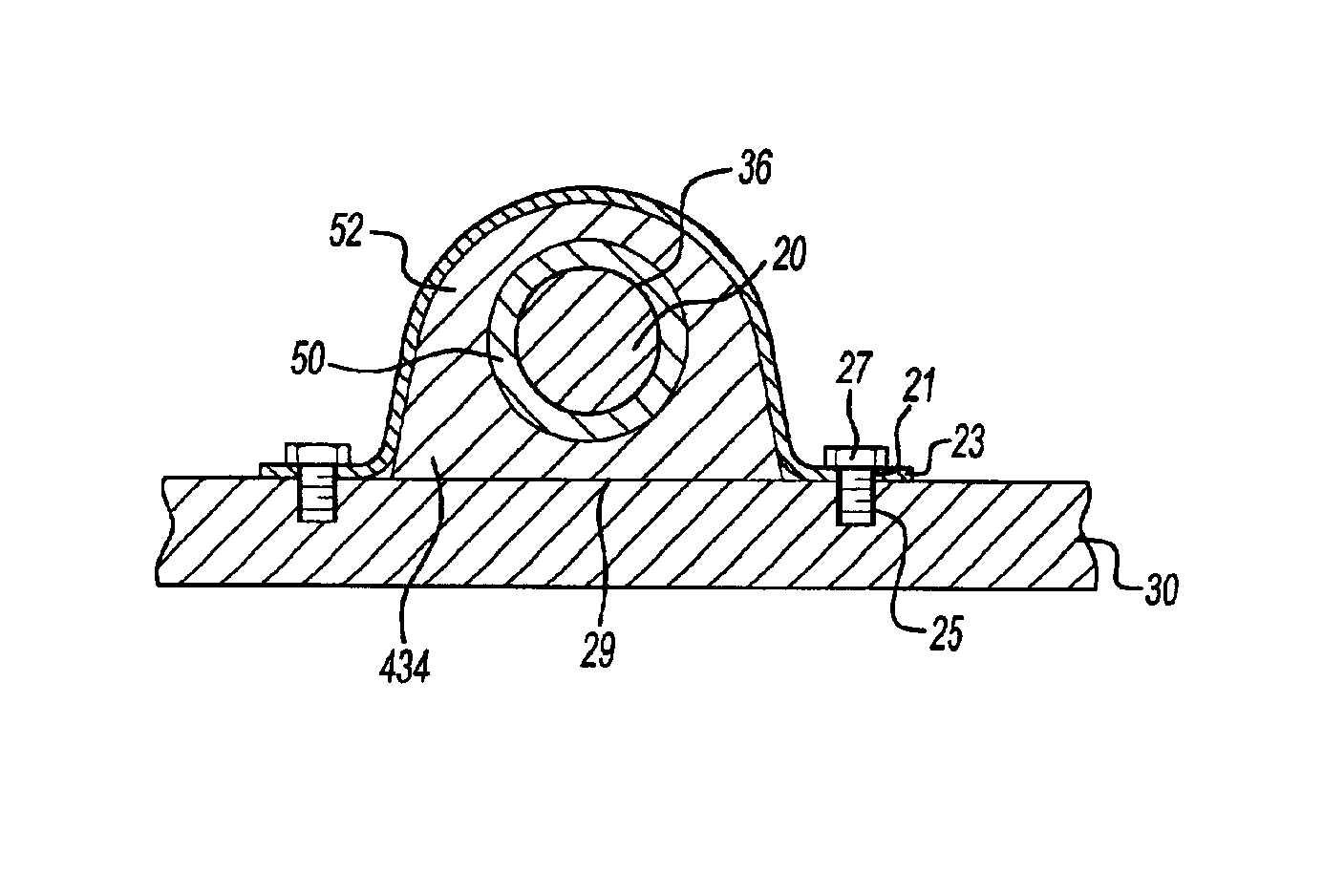
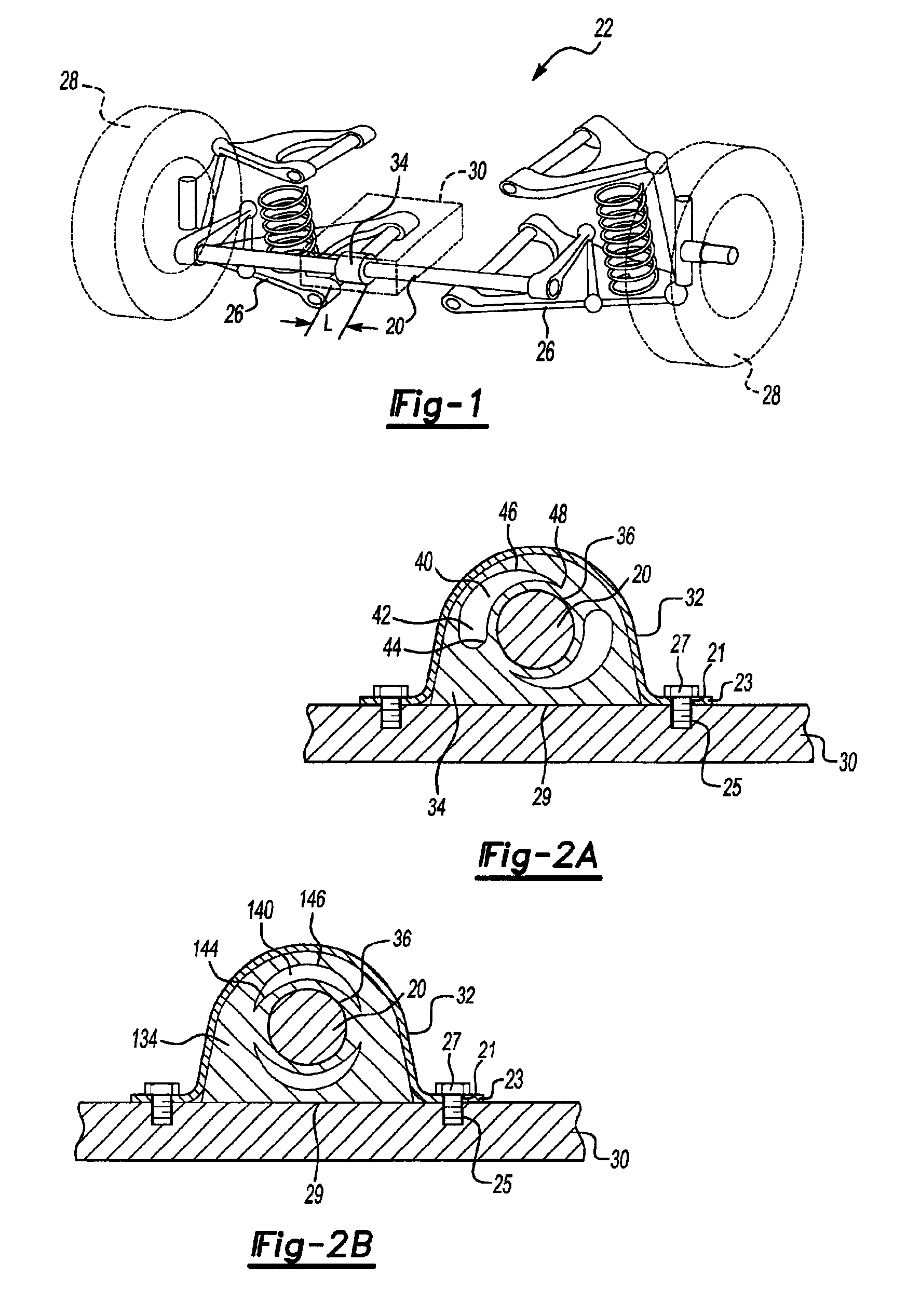
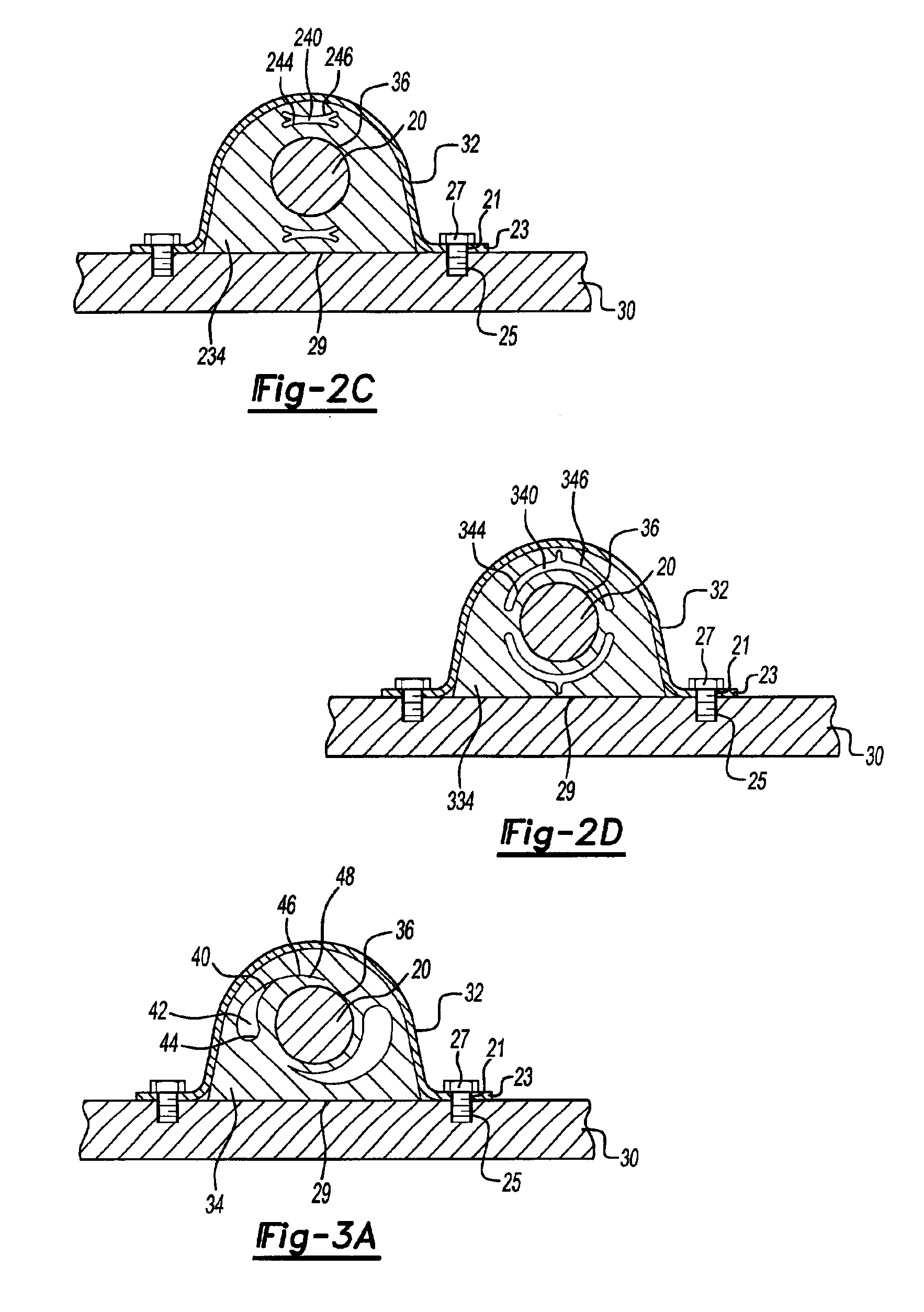
FIG. 1 illustrates a stabilizer bar 20 of a vehicle suspension system 22. As shown, the stabilizer bar 20, or anti-roll bar or anti-sway bar, is attached to control arms 26 which are connected to wheels 28. A variable rate bushing 34 is positioned on the stabilizer bar 20. The stabilizer bar 20 is attached to the vehicle body 30, shown schematically, by a mounting bracket 32 (shown in FIG. 2A) which is positioned over the bushing 34. Although two bushings 34 are illustrated, a worker skilled in the art would recognize that this invention extends to mounts employing more or less bushings 34.

The variable rate bushing 34 of the present invention passively controls the rate and stiffness of the stabilizer bar 20. As shown in FIG. 2A, the bushing 34 is preferably substantially cylindrical in shape and preferably made of rubber or other resilient material. The bushing 34 includes an aperture 36 through which the stabilizer bar 20 passes. When the mounting bracket 32 is positioned over the...


PUM


Abstract

A variable rate bushing passively controls the stiffness of a stabilizer bar. During normal vehicle operation, the stabilizer bar is compliant. As twist increase, the resistance increases. In one embodiment, the variable rate bushing includes at least one void which compresses as the vehicle turns. As the stabilizer bar axially twists, the void compresses and the rate of the bushing increases, reducing axial twist and increasing stiffness of the stabilizer bar. In one embodiment, the voids are teardrop shaped, arc shaped, or bone shaped. Alternatively, the bushing includes an inner layer of softer material and an outer layer of harder material to control stabilizer bar stiffness. Also, the bushing may include a molded insert made of a hard material inserted into a softer material to control the stiffness of the stabilizer bar.

Description

BACKGROUND OF THE INVENTIONThe present invention relates generally to a variable rate bushing utilized on a vehicle stabilizer bar of a vehicle suspension system which passively interacts with the stabilizer bar to minimize vehicle roll.Vehicles are commonly equipped with suspension systems for absorbing road shock and other vibrations, while providing for a smooth and comfortable ride. A suspension component, such as a stabilizer bar, is often used to increase roll rigidity and improve the steering stability of the vehicle. The stabilizer bar is generally attached to the lower A-arms of the suspension system and controls sway as the vehicle turns and provides a pull down force during cornering. This is especially important in sports utility vehicles, which have a higher tendency to roll when the driver attempts an emergency maneuver due to the high center of gravity.As a vehicle turns, the body of the vehicle rolls to the outside of the turn. The suspension components on the outsid...

Claims


Application Information

Patent Timeline
Patent Type & Authority Patents(United States)
IPC IPC(8): B60G11/32B60G11/60B60G21/055B60G21/00F16F1/38
CPCB60G11/60B60G21/0551F16F1/3821B60G2200/144B60G2202/135B60G2204/1222B60G2204/4104B60G2204/41043B60G2202/1424
Inventor CARLSTEDT, ROBERT P.CHAMBERLIN, JAMES B.LEDESMA, RAGNAR H.SAXON, NANCY L.KRAMER, DENNIS A.DOWNEY, DOYLE R.CUBALCHINI, JOSEPHWILLIAMS, MONTE G.
Owner MERITOR LIGHT VEHICLE TECH LLC
Why Eureka
Try Eureka