All electric piezoelectric finger sensor (PEFS) for soft material stiffness measurement

a piezoelectric sensor and soft material technology, applied in the field of piezoelectric sensors, can solve the problems of high false positive rate, destructive mechanical testing of typical tissue/soft material, and none of these techniques can probe the interface properties of tumors

Active Publication Date: 2005-12-15
DREXEL UNIV
View PDF7 Cites 88 Cited by
  • Summary
  • Abstract
  • Description
  • Claims
  • Application Information

AI Technical Summary

Problems solved by technology

Regardless of the mechanism of force / displacement generation and displacement / force detection, typical tissue / soft-material mechanical testing is destructive and it requires specimens cut to a disc shape to fit in the tester.
However none of these techniques have the ability to probe tumor interface properties.
Mammography is the only FDA approved breast cancer screening technique, which has a typical sensitivity of 85% that decreases to 65% in radiodense breasts.10 However, in these screening processes there is a high incidence of false positives.
However, palpation is not quantitative and depends solely on the experience of the individual physician.

Method used


Image

  • All electric piezoelectric finger sensor (PEFS) for soft material stiffness measurement
  • All electric piezoelectric finger sensor (PEFS) for soft material stiffness measurement
  • All electric piezoelectric finger sensor (PEFS) for soft material stiffness measurement

Examples


example 1

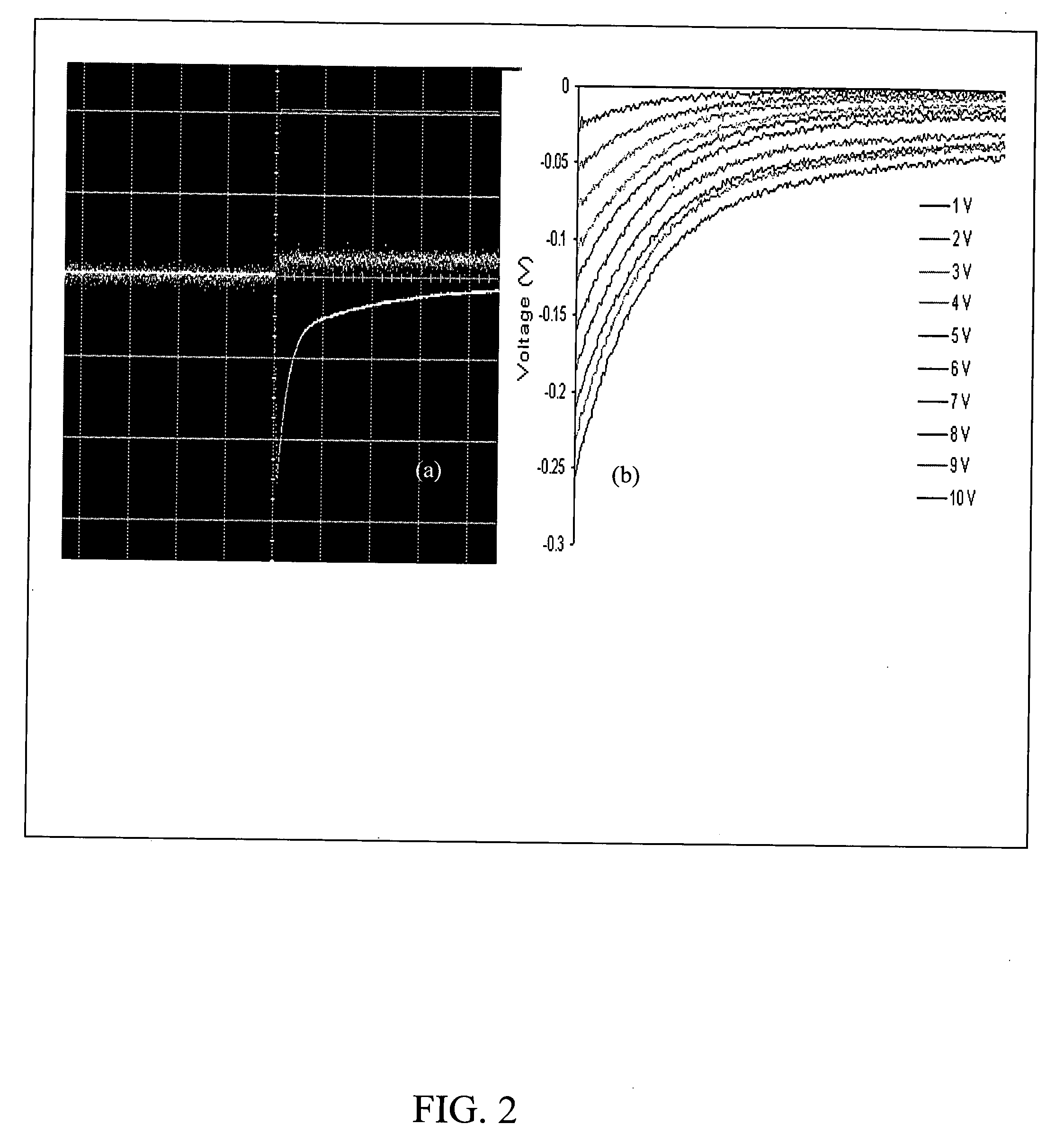
[0043]FIG. 2(a) shows the displacement signal captured by the sensing PZT layer and by the laser displacement meter when a 10V step potential was applied to the unimorph cantilever. FIG. 2(a) shows a typical all-electrical measurement as displayed on an oscilloscope. The applied voltage (line 1), at t=0, indicates the applied voltage was turned on. Line 2 was the voltage output from the laser displacement meter for direct displacement measurements and line 3 was the induced voltage measured at the sensing PZT layer. In FIG. 2(a) the induced voltage was negative. The peak of the induced voltage was therefore at minimum near t=0. The induced voltage decayed with time due to the fact that the PZT layer was not perfectly insulating. The charge generated at the PZT surface by the cantilever bending dissipated over time. As can be seen from FIG. 2(a), the induced-voltage measurement was more sensitive than that generated by the commercial displacement meter (Keynce™ LC2450 displacemeter (...

example 2

Flat-Punch Indentation Compression Test

[0046] A flat-punch indentation compression test is a test whereby the cantilever tip is pressed on the sample surface and the cantilever contact area is much smaller than the sample surface area. This test simulates an in vivo measurement.

[0047]FIG. 4(a) is a representation of an indentation compression test on a model soft tissue using a PEFS with a sensing PZT layer, and FIG. 4(b) is a schematic of the compression indentation test. In the flat-punch indentation compression tests, the contact area, A, which was much smaller than the sample surface, was defined by gluing a thin plastic sheet of a known area on the underside of the cantilever as schematically shown in the setup depicted in FIG. 4(b). Using a traditional Hertzian indentation analysis one can relate load, displacement, contact area, and the mechanical properties of the tested material.17 When applying a voltage to the top, driving PZT layer, it generated a force, F, and caused ...

example 3

Regular Compression Test

[0048] A regular compression test describes a condition where a cantilever is pressed on the sample surface and the contact area is the same as the sample surface area. A schematic of a regular compression test is shown in FIG. 5(a) where the contact area is the same as the surface area. FIG. 5(b) is a schematic of the deformation of a sample in a regular compression test under an applied voltage, V. In a regular compression test, the elastic modulus is obtained by using Ec=K⁡(d0-δ)⁢hA⁢ ⁢δ⁢ ,(3)

wherein h is the height of the sample, d0 the “free” displacement of the cantilever at voltage V, δ the displacement with the sample, K the spring constant of the cantilever and Ec is the elastic modulus measured by the regular compression test. For comparison, the same model tissue sample was tested using both the indentation compression and regular compression test conditions (the left-hand set of data and setup in FIG. 6(a) for regular compression and the right-h...


PUM

PropertyMeasurementUnit
diameteraaaaaaaaaa
diameteraaaaaaaaaa
diameteraaaaaaaaaa

Abstract

A PEFS (Piezoelectric Finger Sensor) acts as an “electronic finger” capable of accurately and non-destructively measuring both the Young's compression modulus and shear modulus of tissues with gentle touches to the surface. The PEFS measures both the Young's compression modulus and shear modulus variations in tissue generating a less than one-millimeter spatial resolution up to a depth of several centimeters. This offers great potential for in-vivo early detection of diseases. A portable hand-held device is also disclosed. The PEF offers superior sensitivity.

Description

[0001] This application claims priority under 35 U.S.C. §119(e) based on U.S. Provisional Application No. 60 / 573,869, filed May 24, 2004, the entire disclosure of which is hereby incorporated by reference as if set forth fully herein.BACKGROUND OF THE INVENTION [0002] 1. Field of Invention [0003] The present invention relates to a piezoelectric sensor for measuring shear and compression. [0004] 2. Brief Description of the Prior Art [0005] A typical soft-material / tissue mechanical property tester requires an external force (displacement) applicator and an external displacement (force) gauge.1,2 The external force (displacement) generator may be hydraulic or piezoelectric and the external displacement gauge (force gauge) may be optical or piezoelectric. Regardless of the mechanism of force / displacement generation and displacement / force detection, typical tissue / soft-material mechanical testing is destructive and it requires specimens cut to a disc shape to fit in the tester. In additi...

Claims


Application Information

Patent Timeline
Patent Type & Authority Applications(United States)
IPC IPC(8): A61B5/103A61B5/117G01N3/00
CPCA61B5/0048G01N19/00A61B5/4312A61B5/441A61B5/442A61B5/444A61B2562/0247A61B2562/046G01N2203/0025G01N2203/0089G01N2203/0094G01N33/4833G01L1/16G01N3/08G01N3/24A61B5/0053A61B5/0057
Inventor SHIH, WAN Y.SHIH, WEI-HENGMARKIDOU, ANNASZWECZYK, STEVEN T.YEGINGIL, HAKKI
Owner DREXEL UNIV
Why Eureka
Try Eureka