Pipe or the like, a female end ring, and a method of manufacturing such a pipe or the like

a technology end ring, which is applied in the direction of fluid pressure sealed joints, joints with sealing surfaces, sleeve/socket joints, etc., can solve the problems of limiting the application of pipe or the like, incompatible with certain installation conditions, and difficult sealing between ferrules and cylinders, etc., to achieve the effect of improving relative sealing

Inactive Publication Date: 2005-02-15
SABLA BONNA
View PDF18 Cites 10 Cited by
  • Summary
  • Abstract
  • Description
  • Claims
  • Application Information

AI Technical Summary

Benefits of technology

To increase the mutual fastening between the ferrule and the cylinder, the inside peripheral face of the ferrule can be fastened to the film constituting the sealing gasket by means of annular adhesive between them, in particular adhesive occupying a continuous annulus, thus also improving relative sealing. To this end, between steps a) and b) of the method of the invention, and after said film has been put into place, a ring of adhesive, in particular a continuous ring, is deposited on a localized zone of said film and / or of said inside peripheral face which is selected in such a manner that when implementing step b) and thereafter said zone constitutes a zone of mutual contact through said adhesive, and of application of said transverse pressure.
Advantageously, if the ferrule of the ring is put into place on the cylinder by progressive forced coaxial engagement of the ferrule on the annular end of said cylinder, the adhesive used for fastening the inside peripheral face of the ferrule with the above-mentioned film and / or for fastening the inside peripheral face of the ferrule with the outside peripheral face of the cylinder is advantageously selected in such a manner that, when in the fresh state, it constitutes a lubricant making said progressive forced engagement easier, while nevertheless being suitable subsequently for providing the desired mutual fastening.

Problems solved by technology

The fastening obtained in that way between the female end ring and the cylinder can be satisfactory providing the precaution is taken of shaping the ferrule in such a manner as to obtain mutual anchoring via complementary shapes, however whatever precautions are taken in this respect, sealing between the ferrule and the cylinder remains problematic, even if sealing is defined merely as an absence of any visible seepage of a liquid placed at a pressure close to ambient pressure going from one side to the other of the gasket between the ferrule and the cylinder.
The use of such bands can limit the applications of the pipe or the like made in that way in that the material from which the bands are made, which material is dictated by considerations of a mechanical nature, can be incompatible with certain installation conditions for the pipe or the like.
Thus, as a general rule, bands are made of steels of a grade that is selected as a function of criteria concerning traction strength and modulus of elasticity, but such seals are generally vulnerable to corrosion and are consequently unusable whenever the pipes or the like are to be buried (unless they are subjected to additional anti-corrosion protection and / or treatment which is expensive and of short-term effectiveness).
Unfortunately, the pressure applied by the bands to the ferrule gives rise to transverse thrust pressure from the ferrule of the female endpiece on the outside peripheral face at the end of the cylinder only through the ferrule, making it necessary to ensure that the ferrule tends to shrink onto the outside peripheral face of the end of the cylinder from a rest condition in which it is engaged on said outside peripheral face.
The ferrule has a natural tendency to oppose such shrinkage from its rest condition so obtaining mutual transverse thrust pressure between the ferrule of the female end ring and the outside peripheral face of the cylinder with sufficient magnitude to ensure effective sealing between them and also to ensure that they are effectively fastened together requires a considerable amount of pressure to be developed between the bands and the ferrule by putting the bands under circumferential tension at the risk of causing irremediable damage to the ferrule.
In practice, the desire to avoid any risk of such damage leads to the magnitude of the circumferential tension in the bands and of the pressure they apply to the ferrule being limited, and the tendency of the ferrule to oppose shrinkage means that the magnitude of the transverse thrust pressure actually applied by the ferrule to the outside peripheral face of the cylinder is even smaller, i.e. not only is fastening between them ineffective, but also the resulting sealing is doubtful.

Method used


Image

  • Pipe or the like, a female end ring, and a method of manufacturing such a pipe or the like
  • Pipe or the like, a female end ring, and a method of manufacturing such a pipe or the like
  • Pipe or the like, a female end ring, and a method of manufacturing such a pipe or the like

Examples


Embodiment Construction

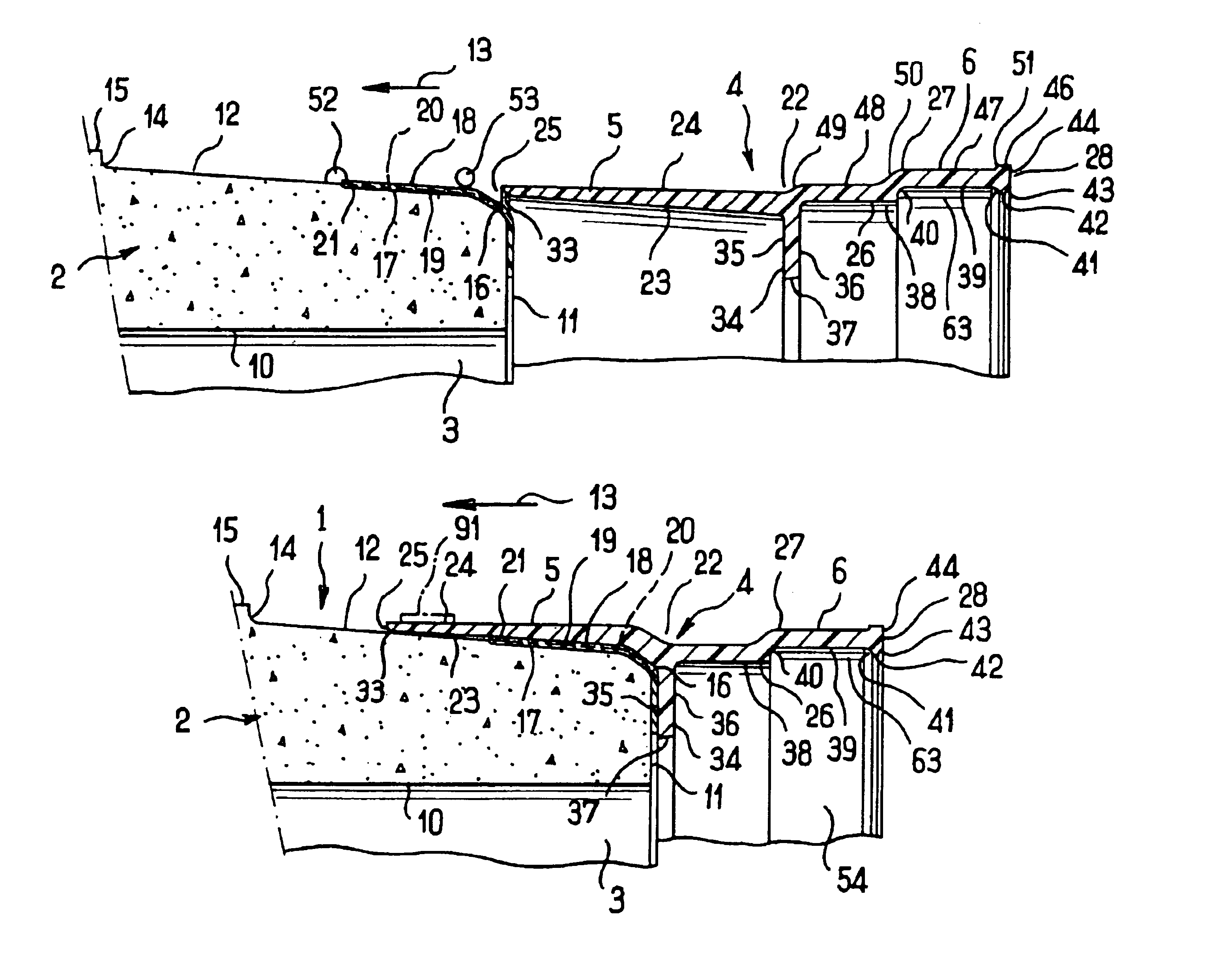
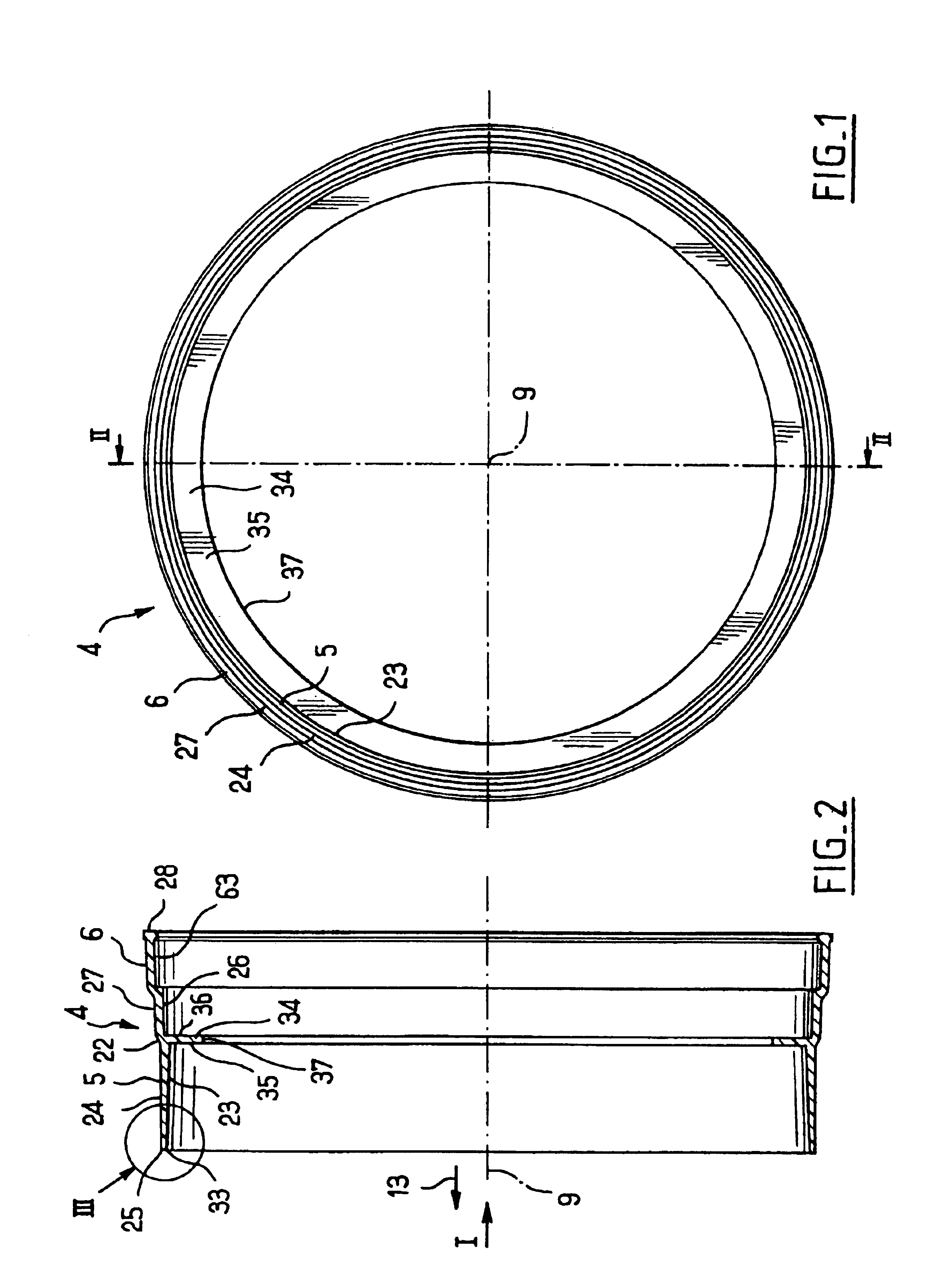
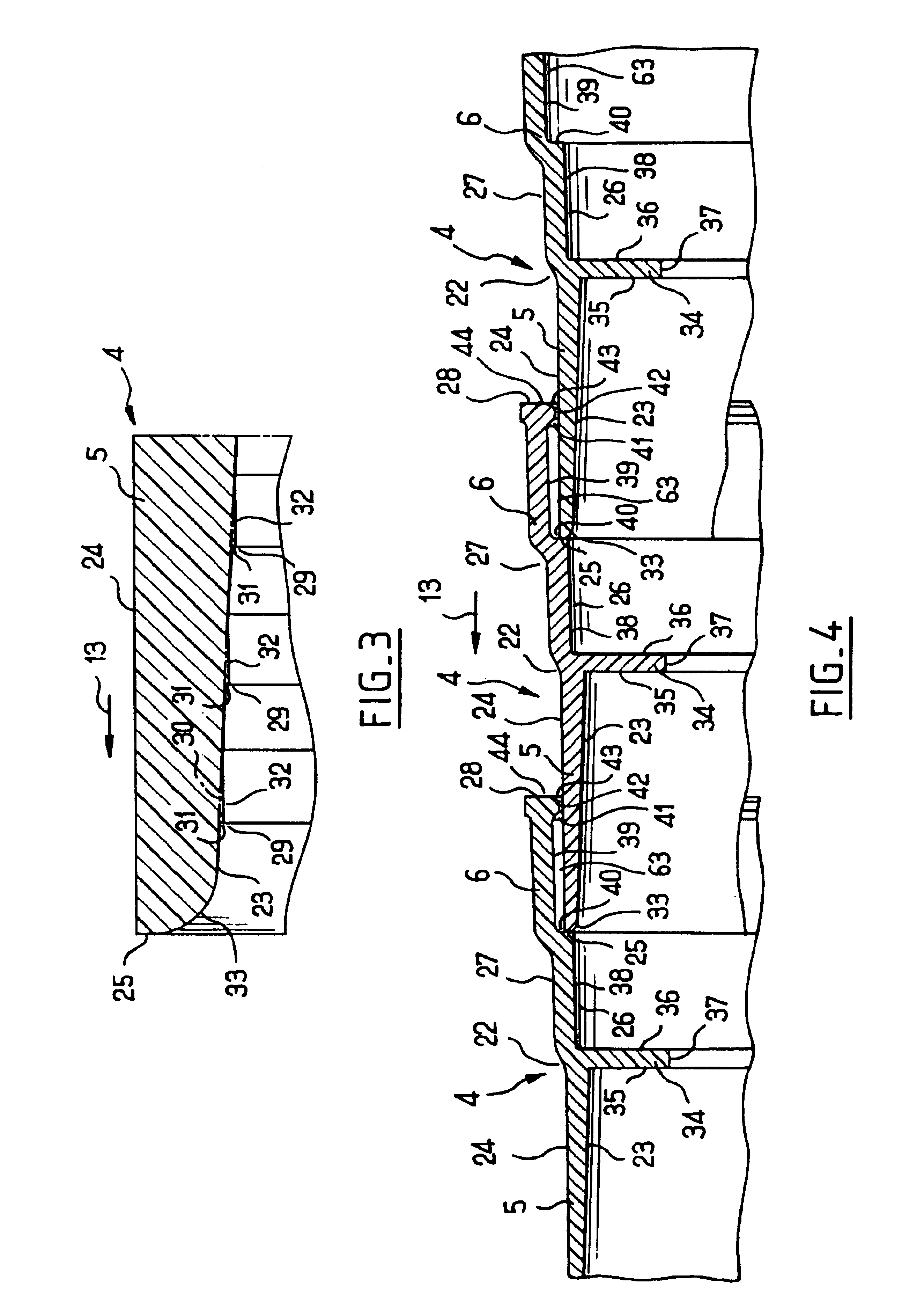
These figures show the invention implemented by making a female endpiece for a pipe in order to provide a leakproof assembly with a male endpiece of another pipe, however a person skilled in the art will readily understand that the present invention can be applied whenever it is necessary mutually to engage in leakproof manner two ducts or other building elements analogous to pipes, in particular those listed in the introduction by way of non-limiting example.

In addition, although the present invention is described below for pipes and female end rings that are both bodies of revolution about a common axis, the invention can also be applied when the pipes or the like present shapes other than being bodies of revolution about their axes, and it comes within the normal aptitudes of a person skilled in the art to adapt the dispositions described below in any manner necessary wherever appropriate.

Insofar as the various implementations of the invention shown in the figures are very analog...


PUM


Abstract

A pipe formed from a concrete cylinder has an end ring with a ferrule which can be snuggly mounted on one end of the pipe and a skirt axially adjacent to the ferrule for receiving a mail endpiece of another pipe. The ferrule is expanded as it is mounted on the cylinder and exerts a compressive force against the outer peripheral face of the cylinder for forming a secure seal. A rib may be disposed on an inner annular surface of the ferrule and an adhesive may be applied for enhancing the seal between the cylinder and the ferrule.

Description

BACKGROUND OF THE INVENTIONThe present invention relates to a pipe or the like, of the type comprising:a concrete cylinder possessing at least one annular end of determined longitudinal axis, defined in particular by a longitudinal outside peripheral face and by a transverse front face;a female end ring coaxial with said end and secured thereto, the ring consisting in:firstly a longitudinal ferrule for securing to the cylinder, the ferrule being defined in particular by a longitudinal inside peripheral face fitting snugly against said outside peripheral face in the immediate vicinity of said front face; andsecondly a longitudinal skirt projecting longitudinally over said front face to engage coaxially on a male endpiece of another pipe or the like.The term “the like” as used herein with respect to pipes means building elements and ducts that can be assembled by being engaged mutually, such as galleries, access holes, so-called “ovoid” interfittable ducting, ducts of the type sold un...

Claims


Application Information

Patent Timeline
Patent Type & Authority Patents(United States)
IPC IPC(8): F16L25/00F16L21/02
CPCF16L25/0027F16L21/022
Inventor LEBLANC, CHARLES FRAN.CEDILLA.OIS
Owner SABLA BONNA
Why Eureka
Try Eureka