Three member thin drawer slide

a three-member, thin technology, applied in the direction of bearings, shafts and bearings, bearings, etc., can solve the problems of reducing the width of the drawer slide, and the failure of the drawer slide to support the load, which is generally unacceptabl

Inactive Publication Date: 2005-02-15
STANDARD PURISHIJIYAN
View PDF34 Cites 58 Cited by
  • Summary
  • Abstract
  • Description
  • Claims
  • Application Information

AI Technical Summary

Benefits of technology

These and other aspects of the present invention will be more readily understood with reference to the following figures and the accompanying detailed description.

Problems solved by technology

Decreasing the width of the drawer slide, however, does create some problems.
Moreover, failure of the drawer slide to support the load is generally unacceptable.

Method used


Image

  • Three member thin drawer slide
  • Three member thin drawer slide
  • Three member thin drawer slide

Examples


Embodiment Construction

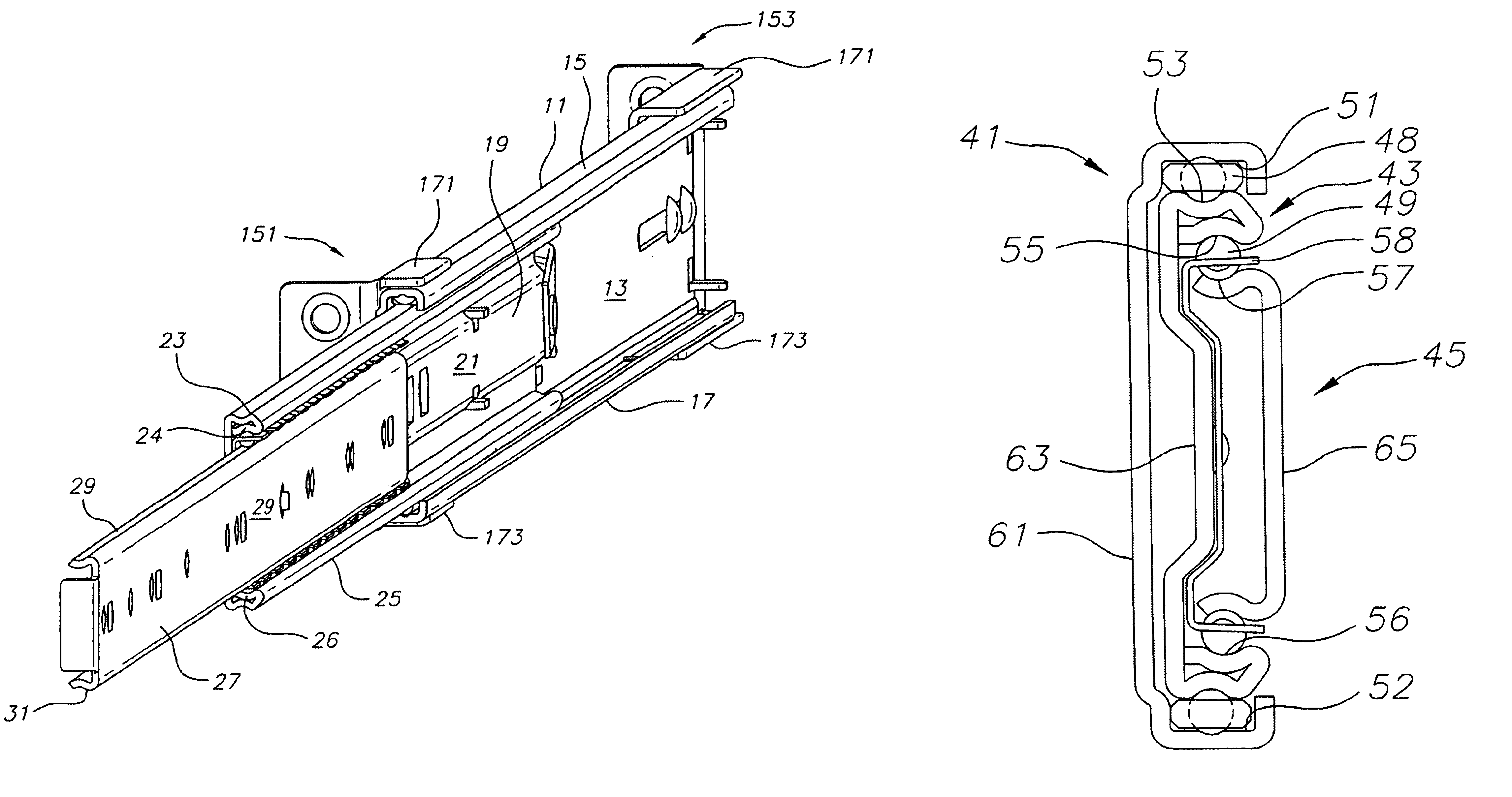
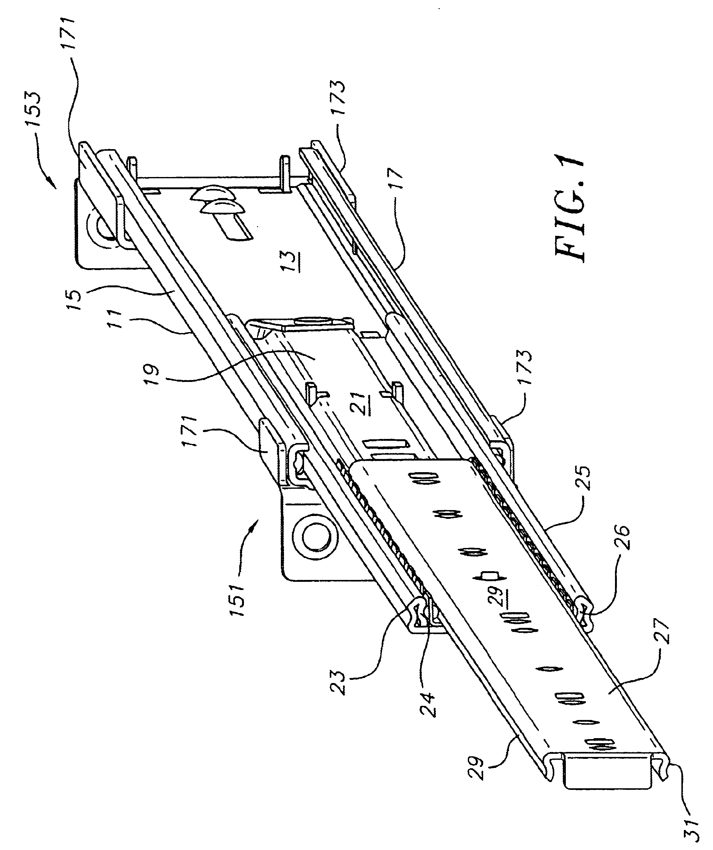
FIG. 1 illustrates a telescopic drawer slide in accordance with the aspects of the present invention. The drawer slide includes an outer member 11. The outer member has a substantially elongate web 13, an upper bearing raceway 15, and a lower bearing raceway 17 along upper and lower margins of the elongate web. The terms “upper”, “lower”, and other directional terms are used for convenience of description, in accordance with the usual mounting of the slide to a cabinet or the like.

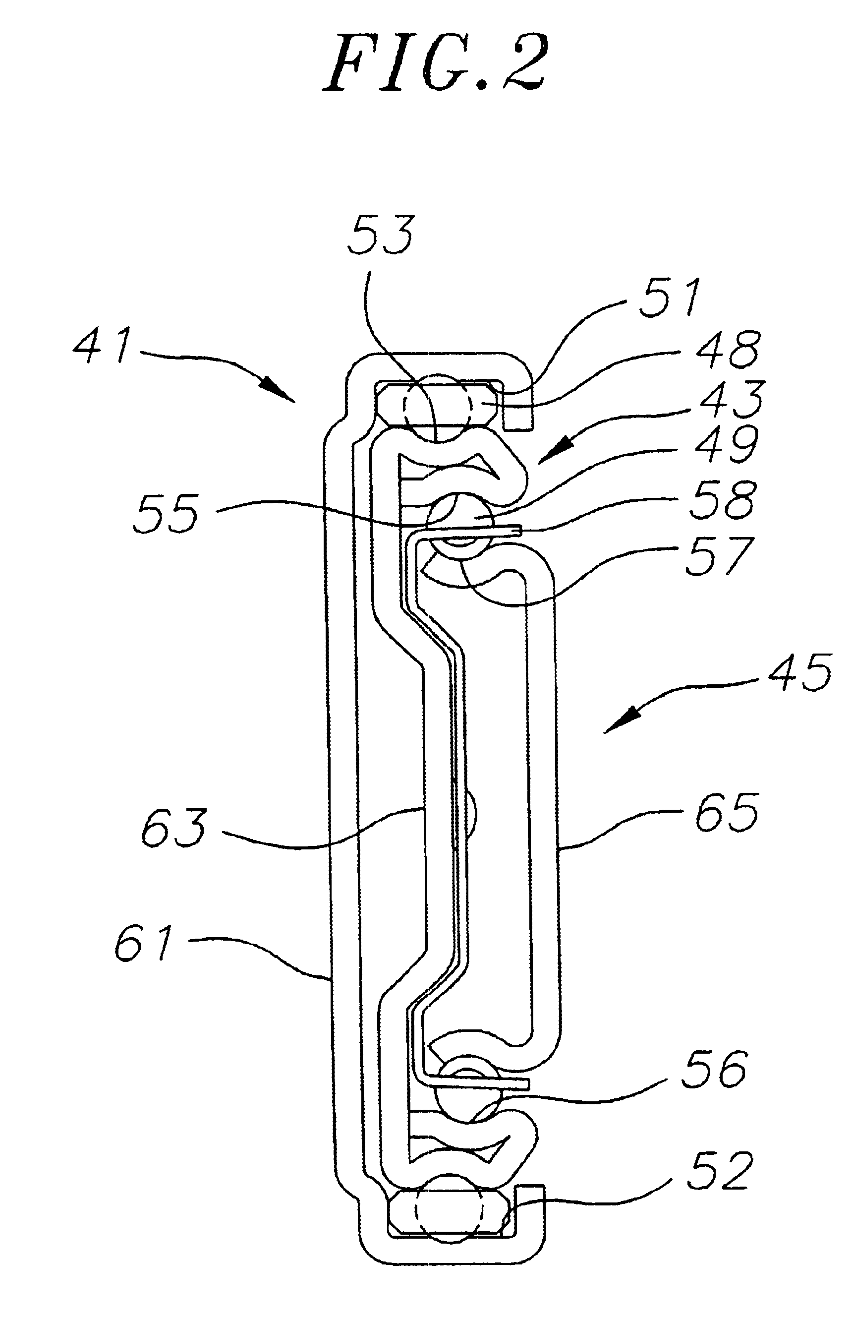
Nestled within the outer slide member is an intermediate slide member 19. The intermediate slide member has a longitudinal elongate web 21. The intermediate slide member has an upper outer bearing raceway 23, an upper inner bearing raceway 24, a lower outer bearing raceway 25, and a lower inner bearing raceway 26, also along the upper and lower longitudinal margins of the elongate web. Nestled within the bearing raceways of the intermediate slide member is an inner slide member 27. The inner slide member h...


PUM


Abstract

A drawer slide assembly with an outer slide member with an elongate planar web including a parallel offset portion, having upper and lower bearing raceways along the length of the web, an intermediate slide member with a elongate planar web, having inner and outer upper and lower bearing raceways along the length of the web, and an inner slide member having an elongate planar web with upper and lower bearing raceways along the length of the web, with bearings disposed between and in rolling engagement with the respective outer and intermediate slide members, and intermediate and inner slide members.

Description

BACKGROUND OF THE INVENTIONThe present invention relates generally to drawer slides, and more particularly to telescopic drawer slides.Drawer slides are often used to extendably couple drawers, trays, and rack-mounted equipment to cabinets, racks and the like. The drawer slides do so by having one elongate member coupled to the cabinet or rack, and another elongate member attached to the drawer or equipment. The elongate members are slidably coupled so as to be able to longitudinally extend with respect to one another. This extension allows easy access to the drawer or equipment.One type of drawer slide is a telescopic drawer slide. A telescopic drawer slide generally has an outer somewhat C-shaped member. An inner member, also generally C-shaped, is generally largely nested within the outer member. At times, an intermediate member is placed between the outer member and the inner member. The inclusion of the intermediate member allows for increased extension of the drawer or equipme...

Claims


Application Information

Patent Timeline
Patent Type & Authority Patents(United States)
IPC IPC(8): A47B88/04A47B88/493
CPCF16C29/063A47B88/044A47B88/43
Inventor MILLIGAN, CHARLES A.
Owner STANDARD PURISHIJIYAN
Why Eureka
Try Eureka