Helmet

Inactive Publication Date: 2005-02-22
SUMITOMO YOSHIYUKI
View PDF14 Cites 7 Cited by
  • Summary
  • Abstract
  • Description
  • Claims
  • Application Information

AI Technical Summary

Benefits of technology

It is preferable that the ventilation hole be formed in a top portion of the helmet body. This, in particular, prevents easy entry of rain into the helmet body.
It is preferable that the guard portion be resilient so as to be capable of bending closer to the ventilation hole while being increasingly loaded with resilience that tends to bring the guard portion back to the original position thereof. This permits impact applied from outside the guard portion to be absorbed to a certain degree by the resilience of the gu

Problems solved by technology

A helmet without ventilation holes, like that shown in FIG. 7, has the disadvantage of tending to contain heat and moisture inside it.
On the other hand, a helmet with ventilation holes 101, like that shown in FIG. 8, has the disadvantage of being less safe, because the ventilation holes 101 diminish

Method used


Image

  • Helmet
  • Helmet
  • Helmet

Examples


Embodiment Construction

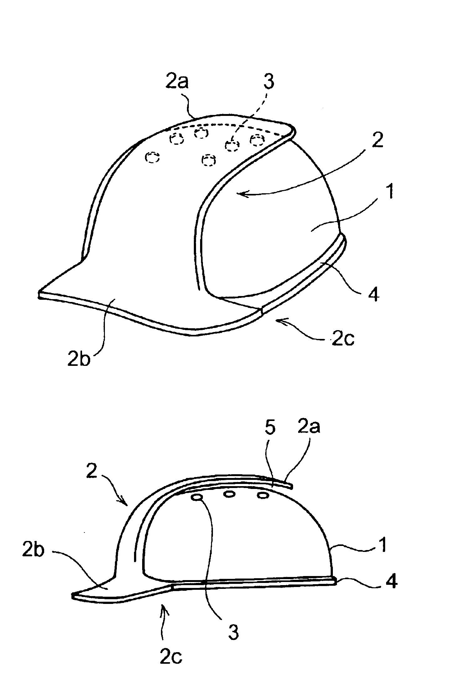
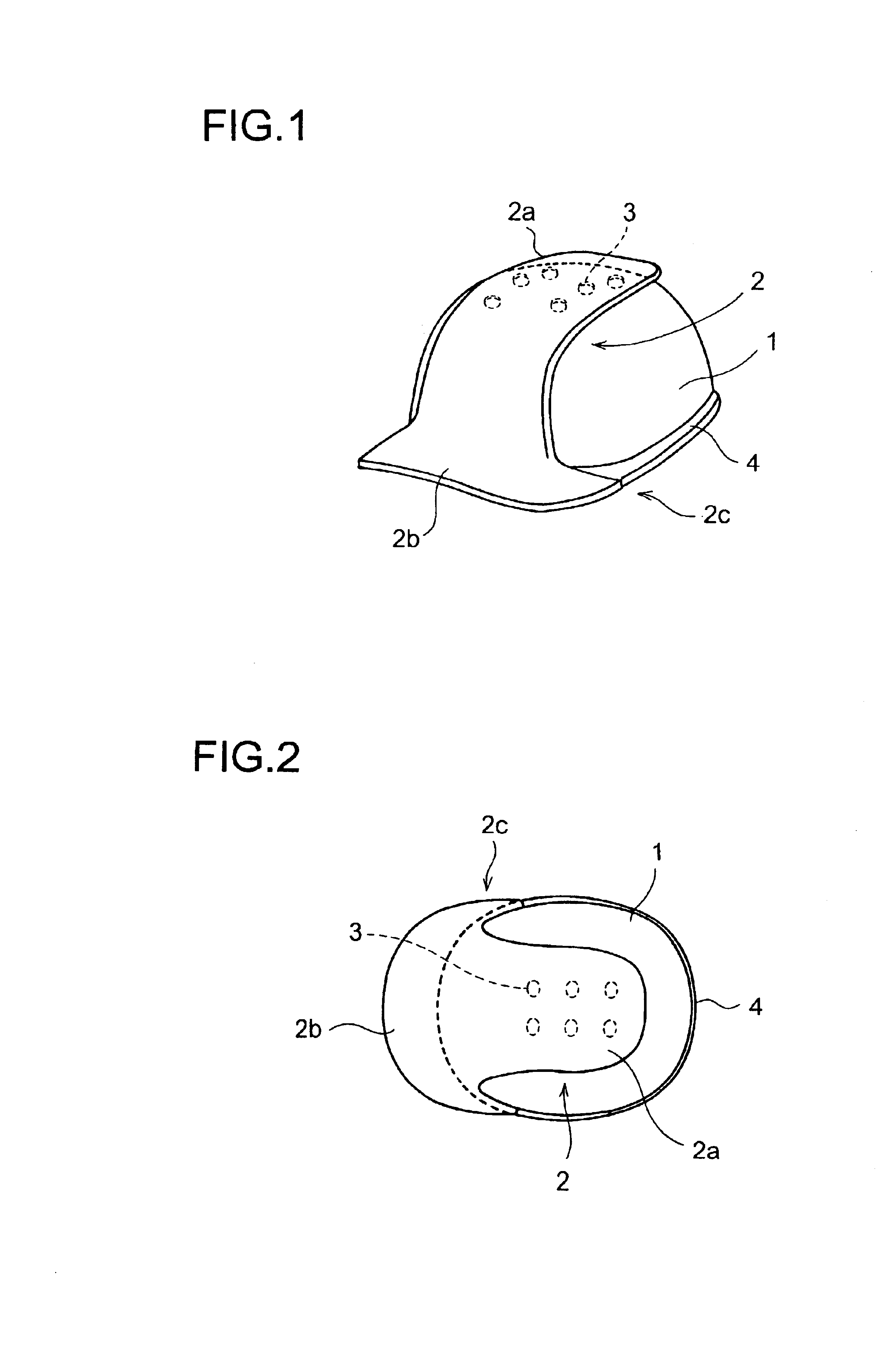
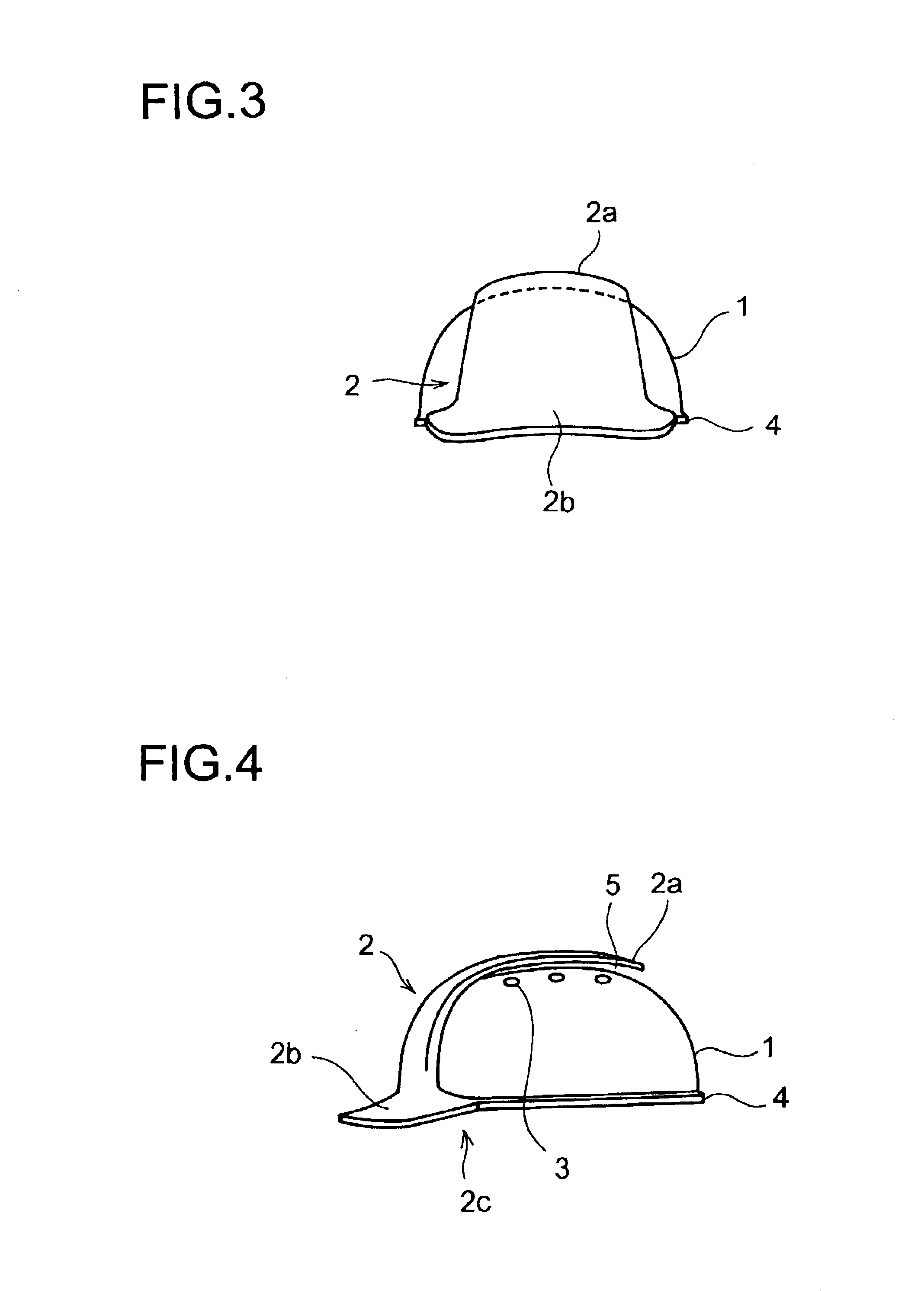
Hereinafter, helmets embodying the present invention will be described with reference to the drawings. FIG. 1 is a perspective view of a helmet embodying the invention, FIG. 2 is a plan view of the helmet shown in FIG. 1, FIG. 3 is a front view of the helmet shown in FIG. 1, FIG. 4 is a side view of the helmet shown in FIG. 1, and FIG. 5 is a side sectional view of the helmet shown in FIG. 1.

The helmet of this embodiment is shaped like a cap with a visor portion 2b. This helmet is provided with a helmet body 1 shaped like a hollow dome and an impact-absorbing plate 2 arranged outside the helmet body 1, both formed of a plastic having appropriate rigidity.

The helmet body 1 is formed so as to cover the upper half of the head of the wearer, and has a plurality of ventilation holes 3 formed in a top portion thereof. Moreover, the helmet body 1 has a flange 4 formed at the bottom end thereof so as to project sideways from all around the circumference thereof.

On the other hand, the impact...


PUM


Abstract

In a helmet, a helmet body 1 has ventilation holes 3 formed therein, and a guard portion 2a is arranged outside the helmet body 1 so as to cover the portion thereof where the ventilation holes 3 are formed. The guard portion 2a has a gap 5 for ventilation secured toward the outer surface of the helmet body 1 and the ventilation holes 3.

Description

BACKGROUND OF THE INVENTION1. Field of the InventionThe present invention relates to a helmet, and more particularly to a helmet having a ventilation hole formed therein.2. Description of the Prior ArtFIG. 7 is a perspective view of an example of a conventional, common helmet, and FIG. 8 is a perspective view of the helmet shown in FIG. 7 with ventilation holes 101 additionally formed therein. A helmet without ventilation holes, like that shown in FIG. 7, has the disadvantage of tending to contain heat and moisture inside it. On the other hand, a helmet with ventilation holes 101, like that shown in FIG. 8, has the disadvantage of being less safe, because the ventilation holes 101 diminish the mechanical strength of the portion of the helmet where they are formed and because the ventilation holes 101 allow a falling object to pass therethrough and directly hit the head of the wearer, and also has the disadvantage of allowing rain to enter the helmet through the ventilation holes 101...

Claims


Application Information

Patent Timeline
IPC IPC(8): A42B3/04A42B3/28
CPCA42B3/281
Inventor SUMITOMO, YOSHIYUKI
Owner SUMITOMO YOSHIYUKI
Why Eureka
Try Eureka