Structure of magnetic buckle

a magnetic buckle and buckle technology, applied in the direction of buckles, snap fasteners, press-button fasteners, etc., can solve the problems of difficult for users to use fingers to press the buckle blocks, the b structure of the conventional buckle is more complicated, and the bb>1/b> will get easily deformed or even broken, so as to facilitate the alignment facilitate the steady insertion of the male buckle, and strengthen the resistance to the buckled state

Inactive Publication Date: 2005-02-22
NIFCO TAIWAN
View PDF5 Cites 79 Cited by
  • Summary
  • Abstract
  • Description
  • Claims
  • Application Information

AI Technical Summary

Benefits of technology

Accordingly, it is an object of the inventor of present invention to provide a brand-new structure of a magnetic buckle that can be positioned promptly and prevented from being slipping off vertically and the same time having a resistance against horizontal pulling external force.
In accordance with the above objects and other advantages of the present invention as broadly embodied and described herein, the present invention provides a structure of buckle comprising a male buckle having a magnetic element, a female buckle having a magnetic element, wherein the magnetic elements of the male and female buckles facilitates the alignment of the male buckle with the female buckle when they are positioned horizontally opposite to each other, as well as facilitates steady insertion of the male buckle into the fit-in groove of the female buckle under the influence of the magnetic attraction.
According to an aspect of the present invention, the buckling element of the male buckle comprises a buckling block, in the fit-in groove of the female buckle comprises a buckling groove for fitting the buckling block of the male buckle, when the buckling element of the male buckle enters the fit-in groove of the female buckle, the male buckle is prevented from slipping off vertically from the female buckle by the external force and this further provide a stronger resistance to the buckled state against any horizontal pulling force.

Problems solved by technology

1. The structure of the conventional buckle is not suitable for applying in smaller articles such as, for example, shoes, watches, belts, and alike. Typically, a user uses fingers to press the buckling blocks B13 of the male buckle B1 that are fitted inside the side openings B22 that are disposed on the two sides of the female buckle B2 in order to release the male buckle B1 from the female buckle B2. However, if the size of the conventional buckle B is made smaller, then space available around the buckle B for the user to use fingers for pressing the buckling blocks B13 of the male buckle B1 will also corresponding smaller, thus it would be very difficult for a user to use the fingers to press the buckling blocks B13 when the size of the male buckle B1 and female buckle B2 is made smaller for applying them in smaller articles such as shoes, watches, belts, and the like.
2. The design of the resilient arms B11 and the alignment arm B12 of the male buckle B1 of the conventional buckle B are extendedly protruded without any support, thus the male buckle B1 would easily hook other near articles while in unbuckled state. Besides, the resilient arms B11 and the alignment arm B12 of the male buckle B1 will get easily deformed or even broken due to excessive external force.
3. The design of the conventional buckle B structure is more complicated, a precise tolerance between the male buckle B1 and female buckle B2 for handling is required, thus it is more difficult to produce such conventional buckle B, and accordingly, the chances of producing flaw items is higher.
4. While pushing the male buckle B1 into the female buckle B2, there is higher possibility of misalignment if the user does not accurately fit the resilient arms B11 and the alignment arm B12 of the male buckle B1 into the openings B21 of the female B2. Thus this would cause difficulty and inconvenient for the user to repeat the action of buckling.

Method used


Image

  • Structure of magnetic buckle
  • Structure of magnetic buckle
  • Structure of magnetic buckle

Examples


Embodiment Construction

Reference will be made in detail to the preferred embodiments of the invention, examples of which are illustrated in the accompanying drawings. Wherever possible, the same reference numbers are used in the drawings and the description to refer to the same or like parts.

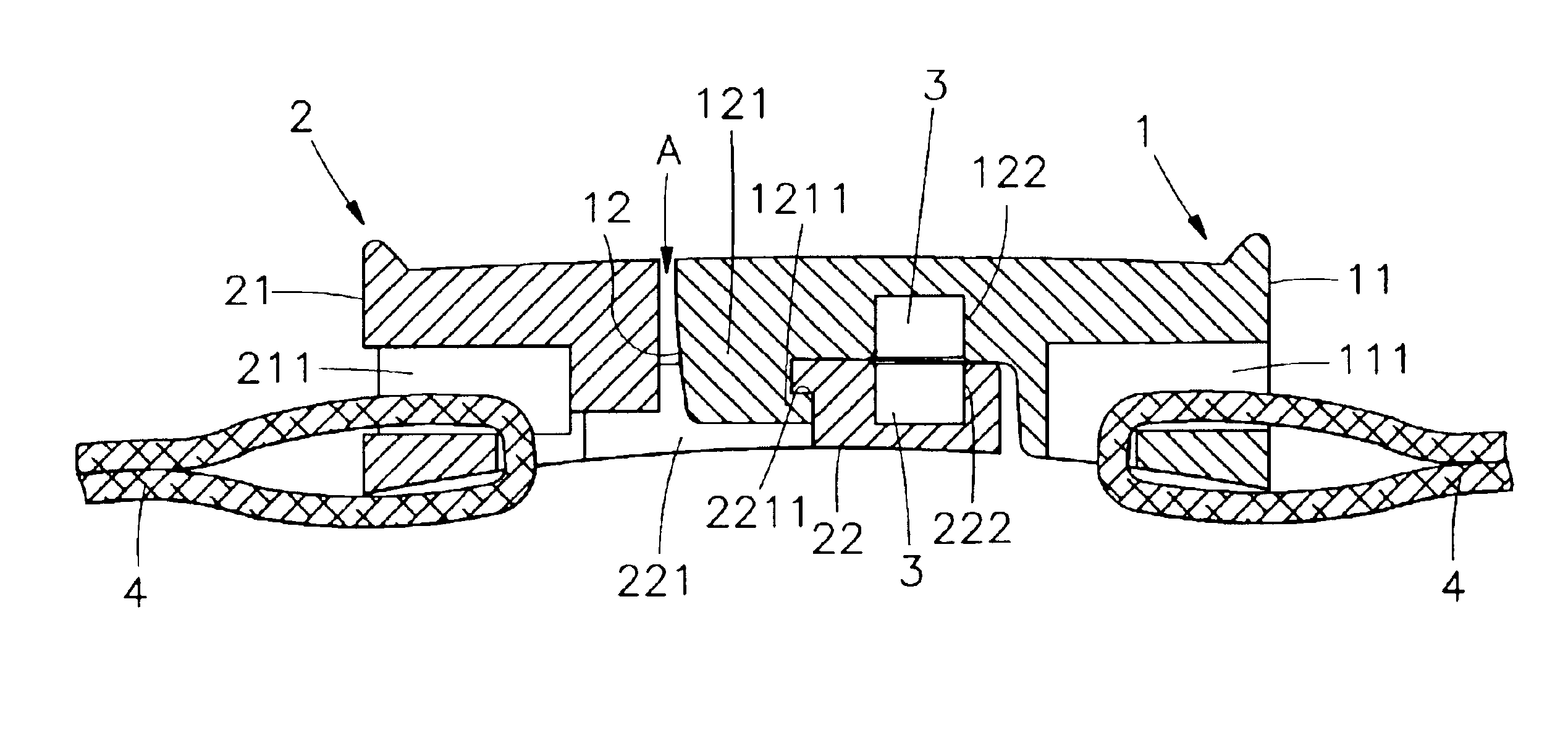
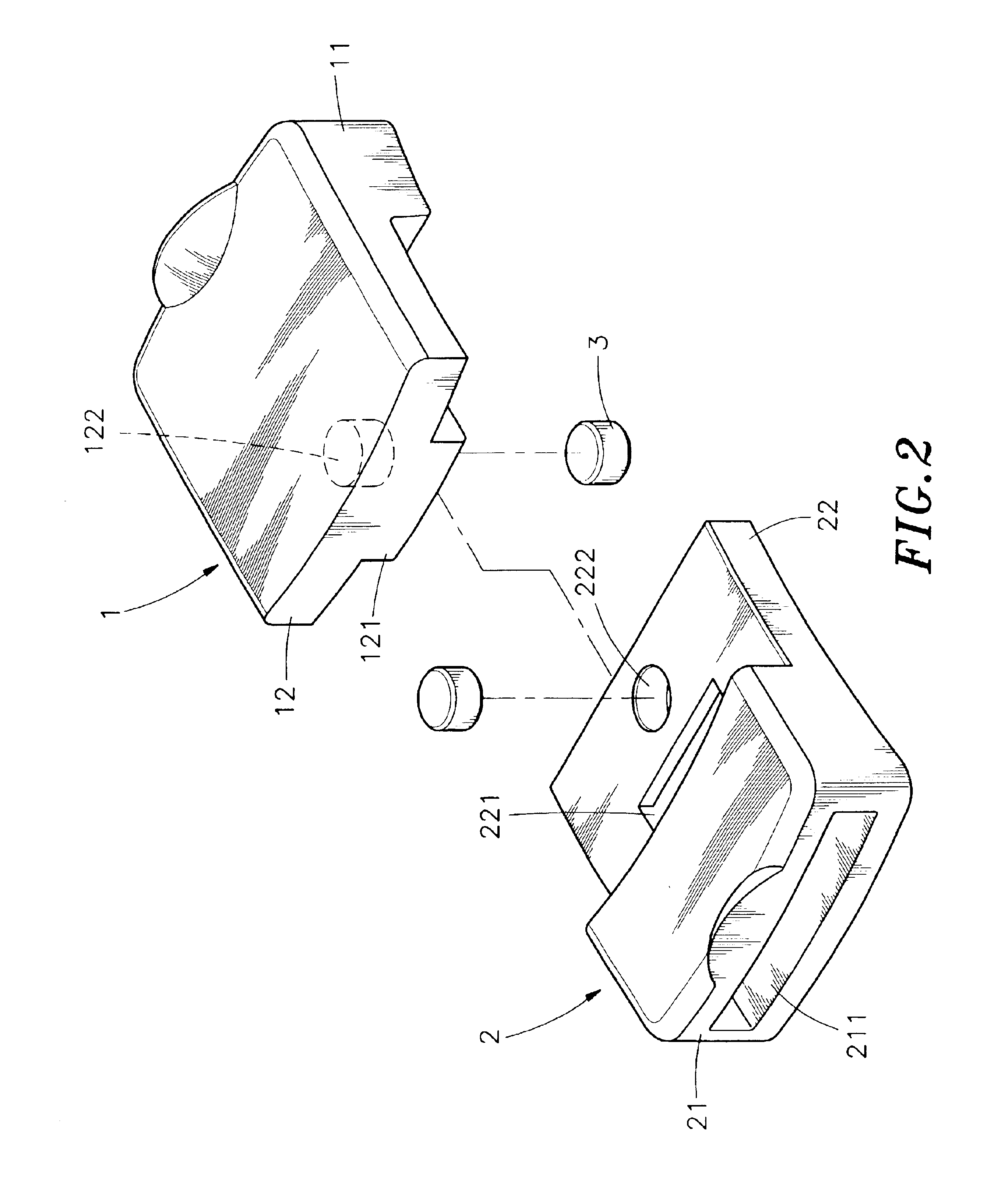
Referring to FIGS. 1, 2 and 3, the magnetic buckle of the present invention comprises a male buckle 1 and a female buckle 2.

The male buckle 1 comprises a base portion 11, a buckling portion 12 is disposed on a flange of the base portion 11, wherein the buckling portion 12 comprises a buckling element 121 at a base part thereof, and a groove 122 at a rear portion of the buckling element 121 for inlaying a magnetic element 3. A protruded buckling block 1211 is disposed on an inner side of the buckling element 121. A through channel 111 is disposed one side of the base portion 11 of the male buckle 1 for fitting and positioning a knitted belt 4.

The female buckle 2 comprises a base portion 21, a buckling portion 22 is dis...


PUM


Abstract

A magnetic buckle. The magnetic buckle includes a male buckle having a magnetic element, and a female buckle having a magnetic element. The magnetic elements of the male and female buckles facilitate the alignment of the male buckle with the female buckle when they are positioned horizontally opposite to each other, as well as the steady insertion of the male buckle into the fit-in groove of the female buckle under the influence of the magnetic attraction. The male buckle can be prevented from slipping off vertically from the female buckle even under an external force, and this arrangement further provides a stronger resistance to the buckled state against any horizontal pulling force.

Description

BACKGROUND OF THE INVENTION1. Field of the InventionThe present invention relates to a structure of magnetic buckle, more particularly relates to a structure of magnetic buckle comprising a male and a female buckle, wherein the male buckle is aligned with the female buckle when the male buckle is positioned opposite to the female buckle by a magnetic attraction and the male buckle can be promptly inserted into the space of the female buckle under the influence of the magnetic attraction.2. Description of the Related ArtA conventional way of securing two ends of a belt together is accomplished by using a buckle. Typically a buckle of a belt comprises a male buckle and a female buckle for securing, for example, a bag, a shoe or a suitcase and the like. Referring to FIGS. 7 and 8 shows a structure of conventional buckle B comprising a male buckle B1 having a resilient arm B11 laterally positioned on each side, and an alignment arm B12 is positioned in between the two resilient arms B11...

Claims


Application Information

Patent Timeline
Patent Type & Authority Patents(United States)
IPC IPC(8): A44B11/25
CPCA44B11/258Y10T24/32A44D2203/00A44B11/2584
Inventor CHUNG, YAO-TSU
Owner NIFCO TAIWAN
Why Eureka
Try Eureka