Extension ring for electrical junction box installations

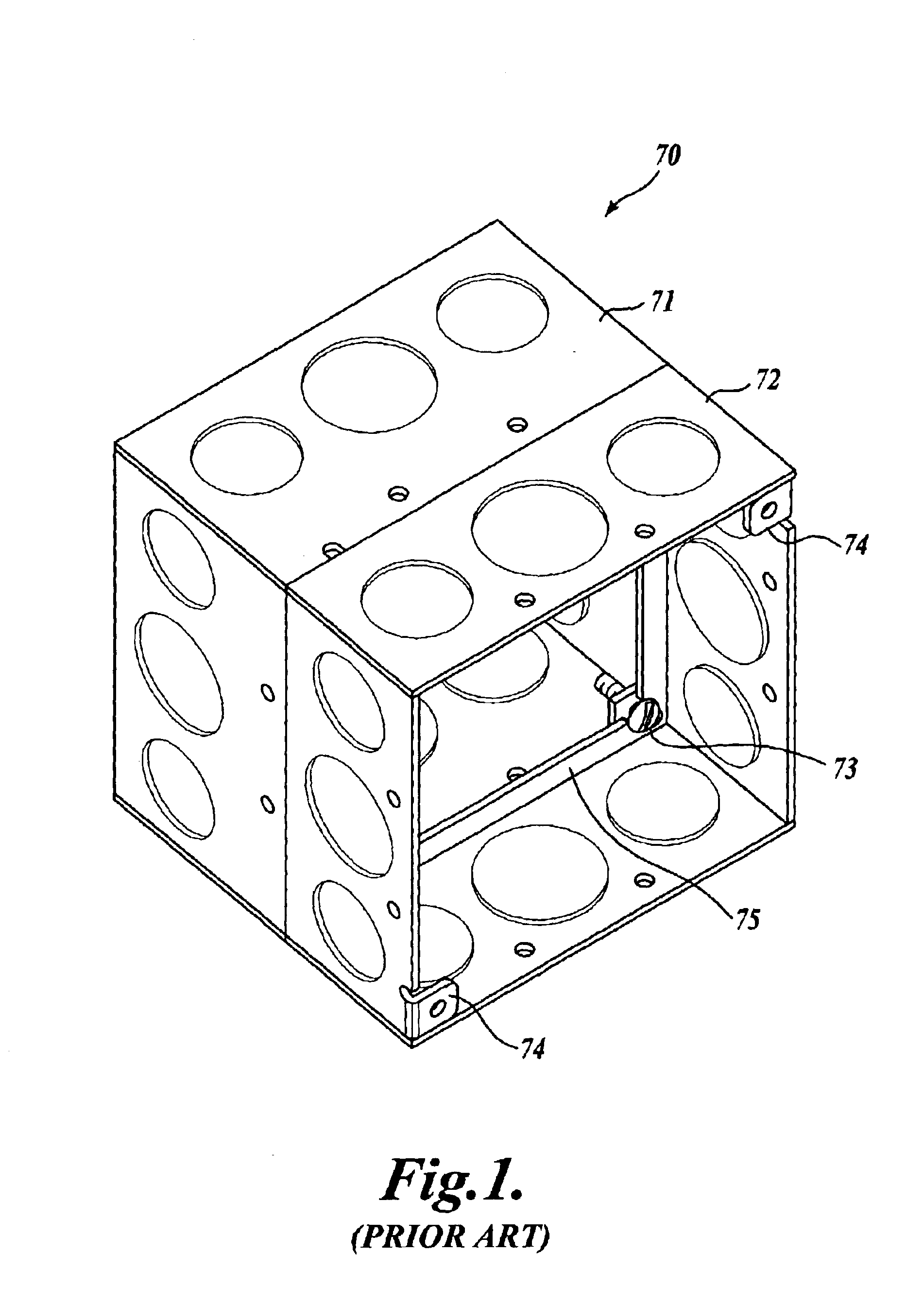
a technology of extension rings and junction boxes, which is applied in the direction of coupling device connections, tumbler/rocker switches, instruments, etc., can solve the problems of insufficient volume inside the extended junction box assembly 70/b>, inability to contain both the alarm signaling unit and the other side of the wall, and small but undesirable bows on the back side of the wall

Inactive Publication Date: 2005-02-22
RANDL IND
View PDF13 Cites 64 Cited by
  • Summary
  • Abstract
  • Description
  • Claims
  • Application Information

AI Technical Summary

Benefits of technology

In an embodiment of the invention the extension ring includes a square outer flange portion and a center portion having a large aperture and a transverse plate including a small threaded aperture, the threaded aperture adapted to receive a mounting screw that is inserted through a corresponding aperture in the alarm signaling unit, to attach the alarm signaling unit to the extension ring.

Problems solved by technology

Conventional junction boxes were inadequate in size to accommodate the alarm signaling units (or similar devices) and the electrical conductors necessary to power the signaling units.
In particular, the available volume inside the extended junction box assembly 70 is still often inadequate to contain both the alarm signaling unit and various electrical conductors that must be accommodated in the box for powering the particular alarm signaling unit and related components (e.g., other alarm signaling units and / or other electrical devices down the line).
In fact, the combined depth of about three and three-quarters inches may cause a small but undesirable bow on the back side of the wall when mounted on a bar hanger.
Contaminate infiltration may provide a safety hazard, as it may cause electrical shorts resulting in a fire or may cause the signaling unit to become inoperative, in addition to causing costly component damage.
A disadvantage to these prior art boxes is that they protrude relatively far from the wall, and they require the conduit coupled to the junction box to be run along an exterior surface of the wall.
Such exterior mounted conduit is unsightly and susceptible to impact damage.

Method used


Image

  • Extension ring for electrical junction box installations
  • Extension ring for electrical junction box installations
  • Extension ring for electrical junction box installations

Examples


Embodiment Construction

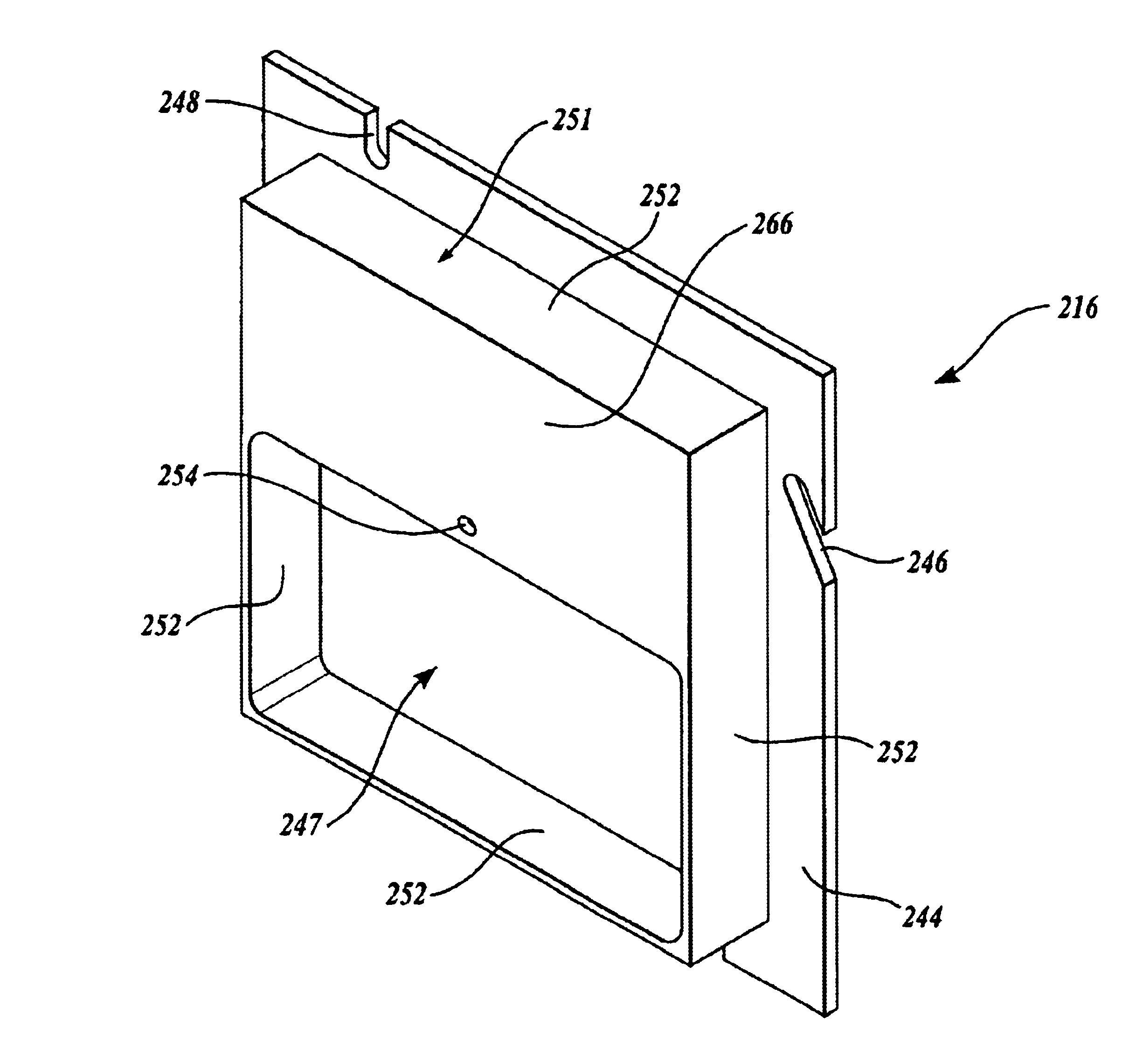
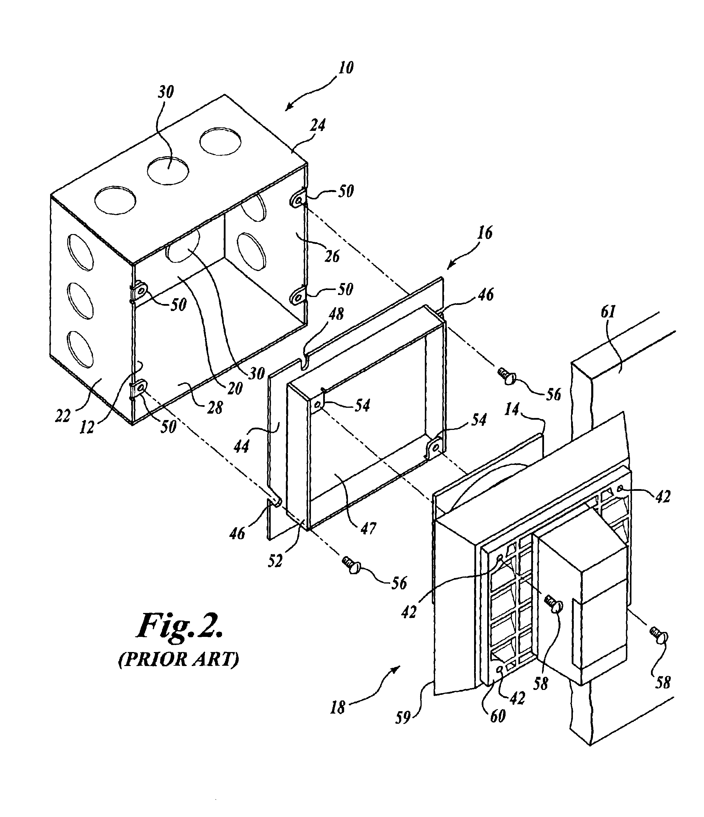
One embodiment of a junction box assembly, and in particular, an extension ring 116 formed in accordance with the present invention is illustrated in FIGS. 3 and 4. Referring to FIG. 3, the improved extension ring 116 provides an interface between a junction box 100 and an alarm signaling unit 118, such as a speaker-strobe signaling unit. The advantages of the extension ring 116 will become more readily appreciated in comparison to a junction box 100 that will be described first, followed by a discussion of the extension ring 116.

The junction box 100 defines a cavity 112 that is designed to receive the wires and a speaker portion 114 or other protruding structure of the signaling unit 118. The cavity 112 is defined by a rear wall 120 and four forwardly-extending sidewalls 122, 124, 126, and 128. In order to accommodate both the speaker portion 114 of the signaling unit 118 and various electrical wires and still fit within the space typically provided between the wall and interior ba...


PUM


Abstract

A junction box assembly for weather-resistant installations is disclosed including a junction box (100) and an extension ring (116, 216) adapted to attach with an component such as an alarm signaling unit (118, 218). The junction box assembly enables a relatively uniform compressive force about the periphery of the alarm signaling unit, such that a good, weather resistant seal is produced between a sealing surface (159, 259) on the alarm signaling unit and a mounting surface (161). In an embodiment of the assembly the extension ring (216) includes a flange (244) that attaches to the junction box, an large aperture (247) providing access to the interior of the junction box, and a mounting plate (266) including a threaded aperture (254) that is centrally located to align with a mounting aperture (242) in the alarm signaling unit. A gasket (219) may be provided between the signaling unit and the sealing surface.

Description

FIELD OF THE INVENTIONThe present invention relates generally to extension rings and, more particularly, to extension rings for weather-resistant mounting of electrical components, such as alarm signaling units.BACKGROUND OF THE INVENTIONConventional electrical junction boxes are four inches square (i.e., four inches on a side) and two and one-eighth inches deep. In approximately 1978, fire alarm signaling units of the type including a strobe light and either an audio speaker or chimes, sometimes called speaker-strobe or chime-strobe alarm signaling units, were introduced. Conventional junction boxes were inadequate in size to accommodate the alarm signaling units (or similar devices) and the electrical conductors necessary to power the signaling units. Accordingly, the industry began to use an extension ring in combination with a conventional junction box, as shown in FIG. 1.The extended junction box assembly 70 includes a conventional four inch by four inch by two and one-eighth i...

Claims


Application Information

Patent Timeline
Patent Type & Authority Patents(United States)
IPC IPC(8): H02G15/10
CPCH02G15/10
Inventor HAGARTY, ROBERT J.WHALEY, MICHAEL T.
Owner RANDL IND
Why Eureka
Try Eureka