Self-sealing filter connection and gas mask filter assembly incorporating the same

a filter assembly and self-sealing technology, which is applied in the direction of breathing filters, breathing masks, breathing protection, etc., can solve the problems of inadvertent inhalation of wearers with the filtration canister removed, depletion of the filtration canister in its ability to effectively filter harmful elements,

Inactive Publication Date: 2005-03-01
AVON PROTECTION SYST
View PDF22 Cites 33 Cited by
  • Summary
  • Abstract
  • Description
  • Claims
  • Application Information

AI Technical Summary

Problems solved by technology

As a gas mask is used in a contaminated environment, the filtration canister will become depleted in its ability to effectively filter harmful elements.
The wearer of the mask often cannot leave the contaminated area, so the filter must be replaced while the wearer remains in the contaminated area.
This presents the problem of ensuring that contaminants are prevented from entering the mask when the filter is removed.
The inhalation valve will therefore have a low opening-pressure, but inadvertent inhalation by the wearer with the filtration canister removed can be disastrous.

Method used


Image

  • Self-sealing filter connection and gas mask filter assembly incorporating the same
  • Self-sealing filter connection and gas mask filter assembly incorporating the same
  • Self-sealing filter connection and gas mask filter assembly incorporating the same

Examples


second embodiment

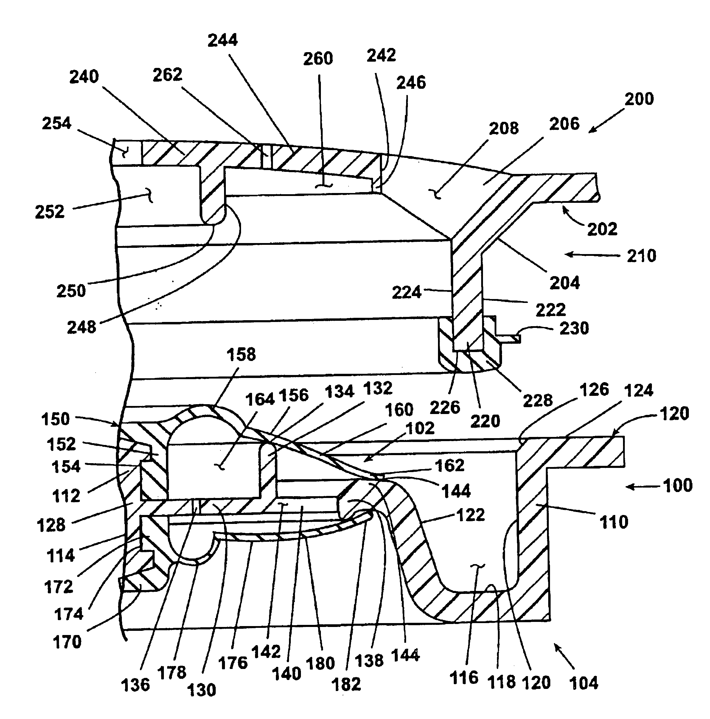
Referring now to FIGS. 8-12, the self sealing valve 100 comprises a valve body 110, a resilient self sealing diaphragm 150, and a resilient inhalation diaphragm 170. Although only a half of the self sealing valve 100 is shown in FIGS. 8 and 9, the other side is a mirror image of the half shown in these drawings. Self sealing valve 100 has an outer face 102 and an inner face 104, the inner face 104 adapted to face the interior chamber of the gas mask 12.

The self-sealing diaphragm 150 is arranged on an outer face of the valve body 110, mounted on a stud 112. The inhalation diaphragm 170 is arranged on an interior face of valve body 110, mounted on a stud 114.

Valve body 110 includes an annular channel 116 having a bottom surface 118, an outer wall 120, and an inner wall 122. Valve body 110 further includes an annulus 124 projecting outwardly from an upper end of channel outer wall 120. The upper end of channel outer wall 120 includes an annular chamfer 126 at an upper end 138. Valve bo...

third embodiment

a self-sealing mechanism 400 according to the invention is shown is FIGS. 13-16. Mechanism 400 comprises a raised perimeter wall 420 having an inwardly projecting lip 416 and defining a central cavity 402 that terminates at a lower portion in a central hub 404 parallel to lip 416. Hub 404 and annular pivot ring 418 are centered in cavity 402 by a plurality of radial spokes 424 connecting hub 404 and pivot ring 418 to lip 416, spokes 424 further defining a plurality of radial openings 426 therebetween. Annular pivot ring 418 comprises an annular upstanding pivot rim 419 perpendicular to the pivot ring 418. Hub 404 further comprises opposing studs 406, 408, perpendicular to the plane defined as the bottom of cavity 402, for receiving conical seal 410 and resilient inhalation valve 428 respectively. Valve 428 is substantially as described above as valve 68 in FIGS. 2-6.

Seal 410 includes a central portion 411, an annular concave hinge portion 412, and a conical skirt portion 414 having ...


PUM


Abstract

A gas mask having a filter canister mount including an inhalation valve and a self-sealing mechanism that prevents air inflow when a filter canister is removed from the canister mount. In one embodiment, the self-sealing valve includes an elastomeric diaphragm mounted in the inlet port and includes a hinge and a skirt, the skirt having a sealing surface that is biased into contact with a valve seat. The filter canister includes a projection adapted to act on the hinge to pivot the skirt away from the sealing surface as the canister is fitted to the canister mount. In one embodiment, the canister comprises a stacked-radial-flow arrangement of particulate and carbon filtration media. In one embodiment, the gas mask includes a visor having a pair of spaced optical panels with a hinge mounted therebetween for relative rotational movement.

Description

BACKGROUND OF THE INVENTION1. Field of the InventionThe invention relates to self-sealing filter connections. In one of its aspects, the invention relates to a self-sealing filter connection for a filter assembly. In another of its aspects, the invention relates to a gas mask with removable filtration cartridges. In another of its aspects, the invention relates to a gas mask with a self-sealing inhalation port valve that is controlled in part by removable filtration cartridges. In another of its aspects, the invention relates to a gas mask with multi-stage filtration cartridges. In another of its aspects, the invention relates to a gas mask with twist and lock removable filtration cartridges.2. Description of the Related ArtU.S. Pat. No. 5,660,173, issued Aug. 26, 1997 to Newton, discloses a filter canister comprising three filter layers. The first layer is a particulate filter preferably made from a glass fiber paper, followed by a carbon bed or beds. The interior surface of the ca...

Claims


Application Information

Patent Timeline
Patent Type & Authority Patents(United States)
IPC IPC(8): A62B23/02A62B23/00A62B7/10A62B18/02A62B9/04A62B18/08
CPCA62B23/02A62B9/04A62B7/10
Inventor CAPON, ANDREWFRIDAY, DAVID K.DAVIS, BRIAN E.PIKE, DAVID W.DUNN, GARY M.
Owner AVON PROTECTION SYST
Why Eureka
Try Eureka