Fluid dispensing arrangement and skid pan for a vehicle

a technology for fluid dispensing and vehicles, applied in the field of vehicles, can solve problems such as not providing any protection

Inactive Publication Date: 2005-03-01
OSHKOSH CORPORATION
View PDF13 Cites 103 Cited by
  • Summary
  • Abstract
  • Description
  • Claims
  • Application Information

AI Technical Summary

Problems solved by technology

The prior art arrangements do not provide any protection for the nozzle arrangements that are mounted at the end of the booms nor do the prior art arrangements allow for convenient, close placement of the nozzle to a fire source or work area.

Method used


Image

  • Fluid dispensing arrangement and skid pan for a vehicle
  • Fluid dispensing arrangement and skid pan for a vehicle
  • Fluid dispensing arrangement and skid pan for a vehicle

Examples


Embodiment Construction

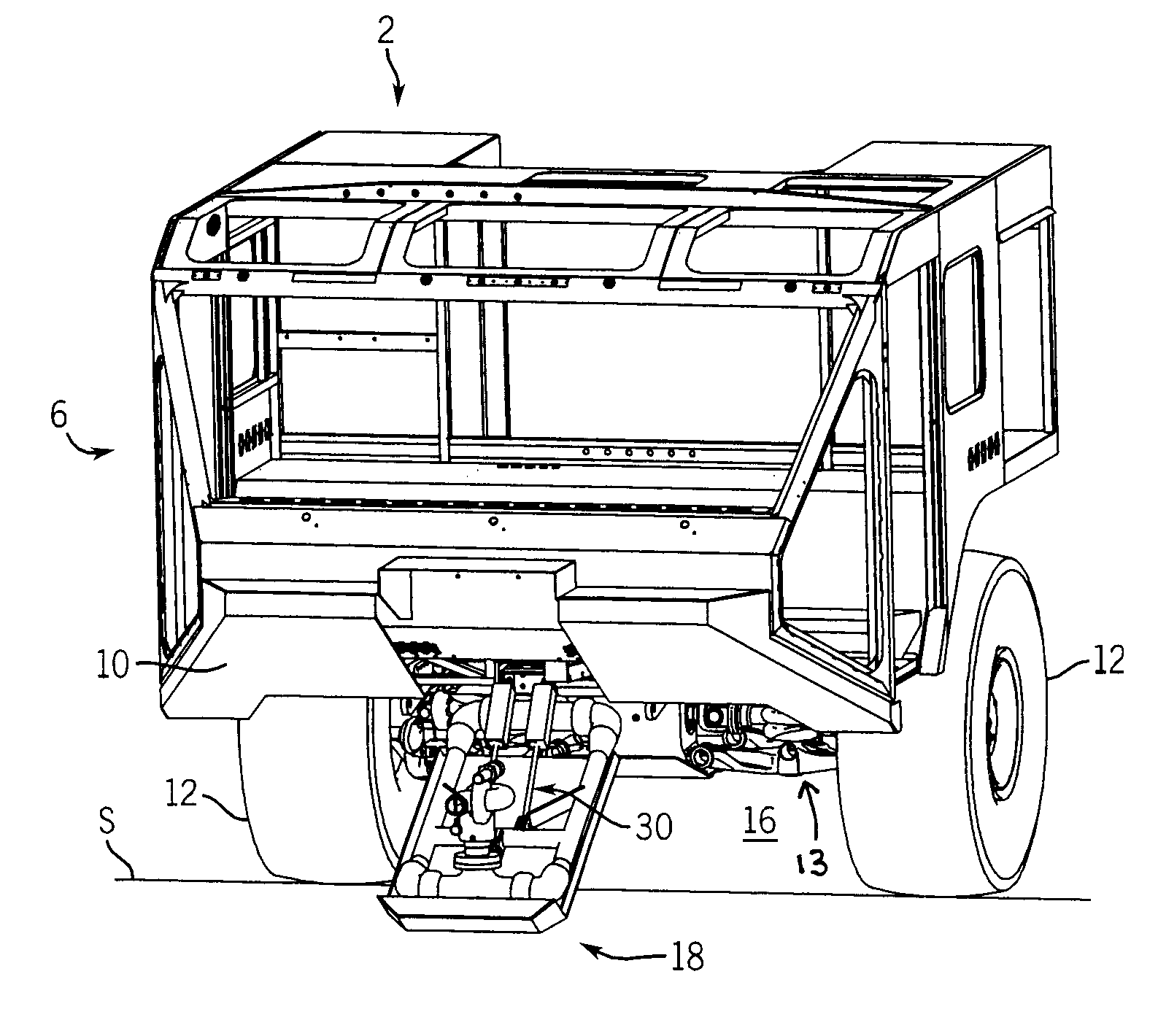
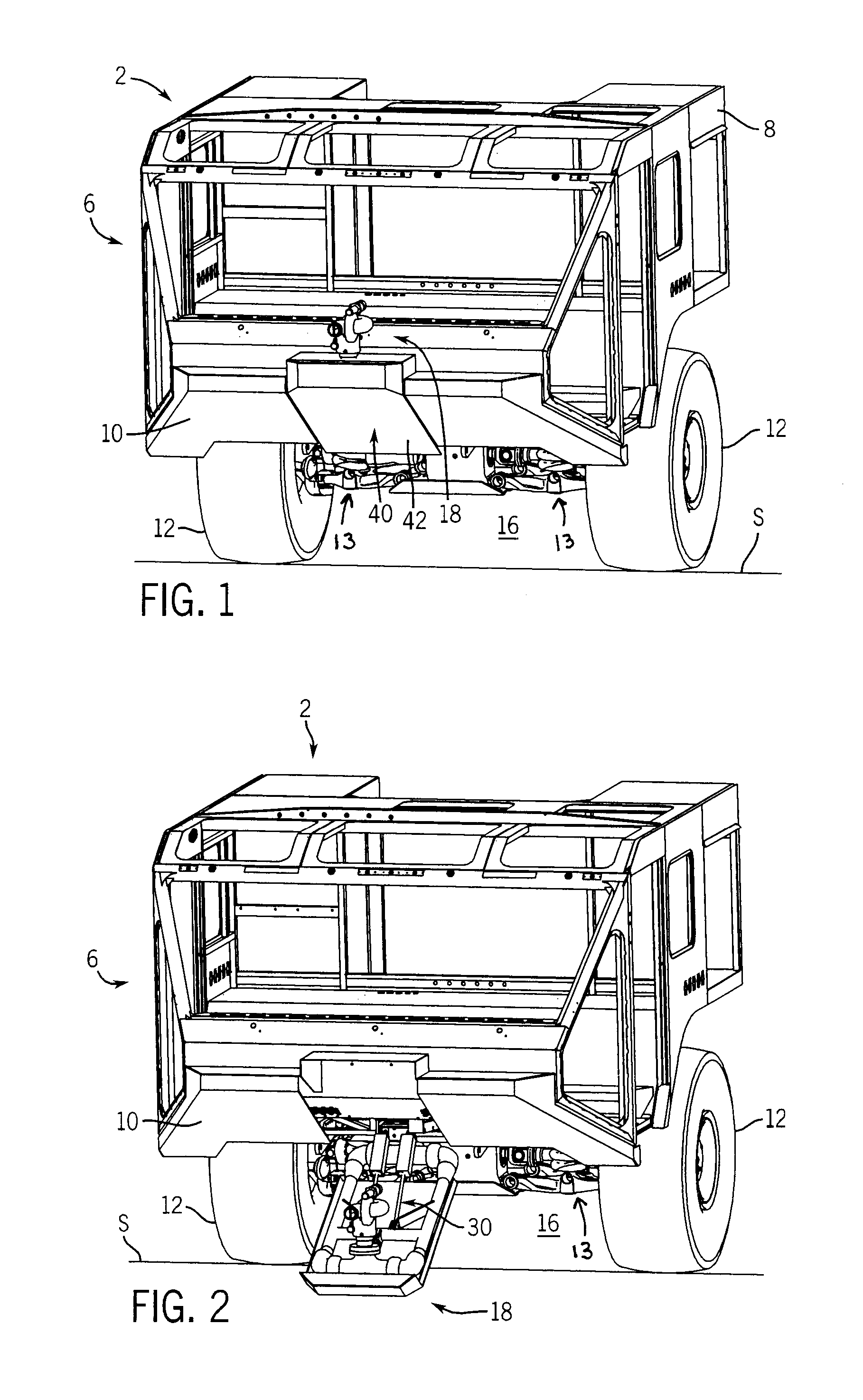
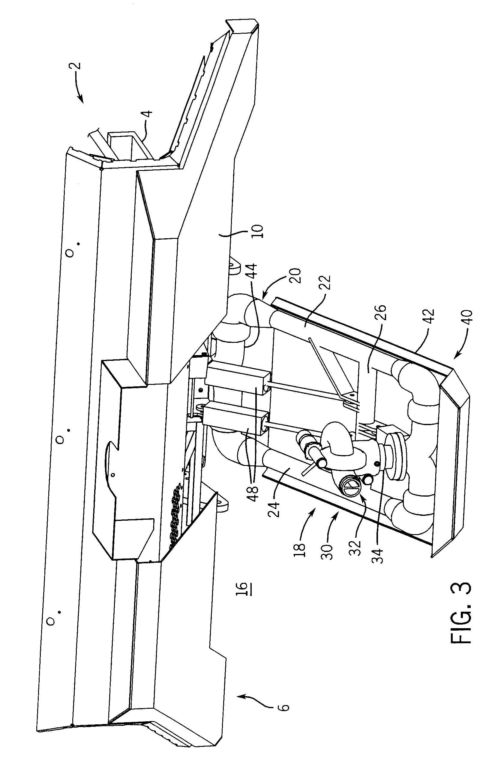
Before discussing exemplary embodiments of the fluid dispensing arrangement and skid pan for a vehicle 2, there are a few preliminary comments. For purposes of this application, the phrase “under-vehicle volume” means that the volume defined by the support structure 4 of a vehicle 2, the plurality of wheels 12 supporting the support structure 4 over a surface S and the surface S itself. It is contemplated that the outside plane of each wheel 12 and the outermost plane of the vehicle body 10 will be used to establish the perimeter lines for four of the under-vehicle volume boundaries. The underside of the vehicle 2, typically the frame 4 and / or vehicle body 10 portions will be used for a boundary and the surface that the vehicle 2 is over provides the sixth boundary defining the under-vehicle volume 16. As will be appreciated, the volume is not fixed but will vary with the shape of the vehicle 2 and the surface S over which it is located.

When referring to a vehicle 2, it is contempla...


PUM


Abstract

A fluid dispensing arrangement and skid pan for use with a fire fighting vehicle, with the vehicle defining an under-vehicle volume. The fluid dispensing arrangement comprises a fluid source, a nozzle support coupled to the vehicle and movable within at least a part of the under-vehicle volume. A nozzle assembly is supported by the nozzle support and is in fluid communication with a fluid source. An actuator is coupled to the nozzle support to move the nozzle support within at least a part of the under-vehicle volume.

Description

BACKGROUND OF THE INVENTIONThe invention relates to vehicles in general and in particular to a fluid dispensing arrangement for use with a vehicle and a skid pan for protection of a device coupled to a vehicle.Prior art vehicles utilizing fluid dispensing devices typically have been in fire fighting vehicles having aerial lifts and fluid nozzles on an outer end of a boom mechanism. Typically, the booms are mounted on the top side of the vehicle at about its midsection. The boom then articulates or telescopes to various positions which can include in front of the vehicle. Prior art arrangements also include a bumper mounted fluid dispensing nozzle that is mounted on a telescoping boom coupled to the front of a fire vehicle or fixed on the front bumper of the vehicle.The prior art arrangements do not provide any protection for the nozzle arrangements that are mounted at the end of the booms nor do the prior art arrangements allow for convenient, close placement of the nozzle to a fire...

Claims


Application Information

Patent Timeline
Patent Type & Authority Patents(United States)
IPC IPC(8): A62C27/00
CPCA62C27/00
Inventor ARCHER, DAVID W.ROWE, RYAN F.
Owner OSHKOSH CORPORATION
Why Eureka
Try Eureka