Image display panel manufacturing method, image display device manufacturing method, and image disiplay device

a technology of image display panel and manufacturing method, which is applied in the direction of liquid/fluent solid measurement, fluid pressure measurement, peptide, etc., can solve the problems of lack of imaging repetition stability, slow response rate, and difficulty in maintaining a stable dispersion sta

Inactive Publication Date: 2006-10-19
BRIDGESTONE CORP
View PDF2 Cites 106 Cited by
  • Summary
  • Abstract
  • Description
  • Claims
  • Application Information

AI Technical Summary

Benefits of technology

[0010] The present invention has for its object to eliminate the drawbacks mentioned above and to provide a method of manufacturing the image display panel, which can seal the liquid powders or the particles uniformly in a plurality of cells even when two of more kinds of the liquid powders or the particles are to be scaled. Particularly, the present invention has for its object to provide a method of manufacturing an image display panel, which can prevent liquid powders or particles remaining in the boundary, liquid powders or particles flying and a liquid powder layer or particle layer deviation when two substrates are stacked after the liquid powders or the particles are equally and uniformly arranged in a plurality of cells formed by the partition walls arranged on the substrate.

Problems solved by technology

However, in the electrophoresis method, there is a problem that a response rate is slow by the reason of viscosity resistance because the particles migrate among the electrophoresis solution.
Further, there is a problem of lacking imaging repetition stability, because particles with high specific gravity of titanium oxide is scattered within solution of low specific gravity, it is easy to subside, difficult to maintain a stability of dispersion state.
Even in the case of microencapsulating, cell size is diminished to a microcapsule level in order to make it hard to appear, however, an essential problem was not overcome at all.
[The Imaging Society of Japan “Japan Hardcopy “99” (Jul. 21-23, 1999) Transaction Pages 249-252) However, the structure becomes complicated because the charge transport layer and further a charge generation layer are to be arranged.
In addition, it is difficult to constantly dissipate charges from the electro-conductive particles, and thus there is a drawback on the lack of stability.
However, in the dry type image display device having the construction mentioned above, a manufacturing method is not generally established, and further it is not established a technique for sealing the particles or the liquid powders equally and uniformly between the substrates, which is an especially important step in the manufacturing method.
Here, if the step of sealing the particles or the liquid powders does not satisfy the above conditions, there occur various problems such as a color shading, a chipped image, a variation of image response speed due to an unevenness of distance between the substrates, an increase of driving voltage for flying and moving the particles or the liquid powders and so on.
Among them, in the roll coater application method, since it is difficult to adhere the particles to the substrate, it is liable to generate a shortage of filling amount (applying amount) of the particles and a deviation of density.
Also, in the particle immersion method, since it is difficult to adhere the particles to the substrate, it is liable to generate a shortage of filling amount of the particles.
In addition, since the particles are not firmly secured to the substrate, it is liable to generate a particle flying and a particle deviation due to a shock or a wind pressure when two substrates are stacked.
Therefore, both methods are not sufficient for sealing the particles.
Therefore, when two substrates are stacked, there is a case such that the particles remain in a boundary between the substrate and the partition wall or in a boundary between the partition walls, and thus there is a problem such that a distance between the substrates is node made even.
In addition, there is no idea for a method of sealing the liquid powders between the substrates equally and uniformly.
In the known manufacturing method mentioned above, the connection between the substrate and the partition wall has a sufficient strength in the case that a glass substrate is used as the transparent substrate and the opposed substrate, but the connection mentioned above does not have a sufficient strength if use is made of the other transparent substrate such as a resin substrate.
Furthermore, it is not known the suitable method for forming a module of circuits such as a driver used for an image display.

Method used


Image

  • Image display panel manufacturing method, image display device manufacturing method, and image disiplay device
  • Image display panel manufacturing method, image display device manufacturing method, and image disiplay device
  • Image display panel manufacturing method, image display device manufacturing method, and image disiplay device

Examples


first embodiment

As to the Method of Manufacturing the Image Display Device

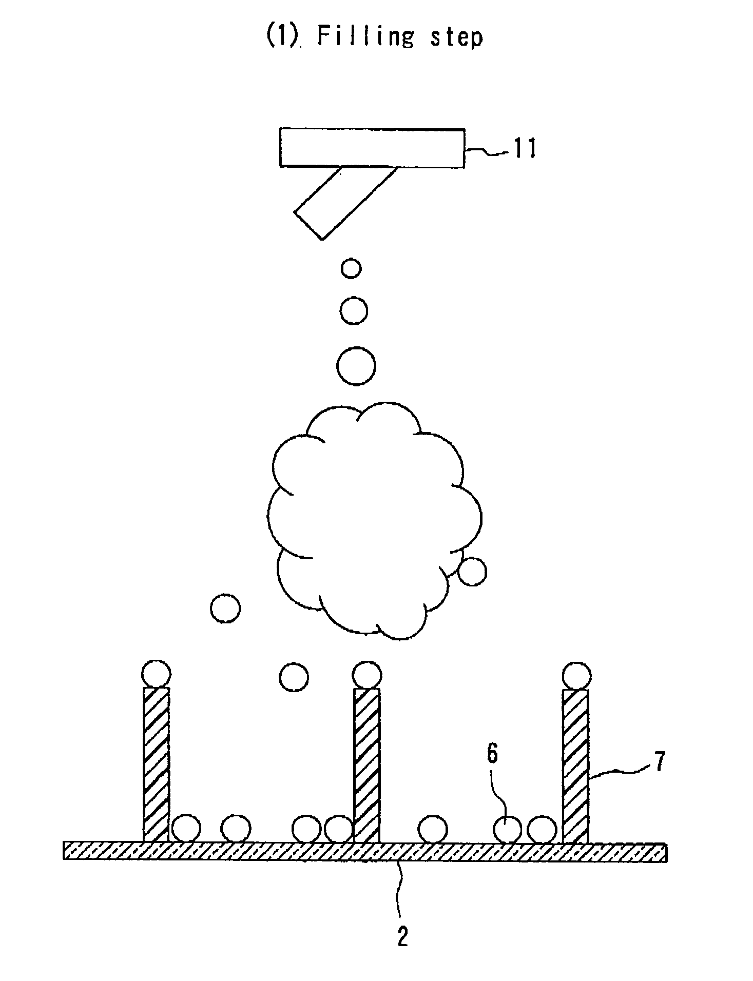
[0068] Hereinafter, respective steps, which are features of the first embodiment of the method of manufacturing the image display device according to the invention, will be explained. It should be noted that the explanation is made to the liquid powders as one example in the explanation mentioned below, but it is possible to utilize the same filling steps for the liquid powders as it is with respect to the method of filling the particles if the liquid powders are exchanged to the particles.

[0069] The features on the first embodiment of the method of manufacturing the image display device according to the invention are to combine a liquid powder filling step, a liquid powder removing step, a substrate stacking step and an electrode adhering step, when manufacturing the image display device having the construction mentioned above. It should be noted that, in the embodiments mentioned below, the explanation is made to a monoton...

example 1

Liquid Powders

[0165] The image display panel was manufactured as follows.

[0166] At first, a substrate (7cm×7cm) with an electrode was prepared, and on the substrate, a rib having a height of 400 μm was produced to form a partition wall having a stripe shape.

[0167] The production of the rib was performed as follows. As an inorganic powder, a glass powder was prepared by melting, cooling and grinding a mixture of SiO2, Al2O3, Bi2O3, Bi2O3, and ZnO. As a resin, epoxy resin having a heat hardening property was prepared. Then, the glass powder and the epoxy resin were mixed with a solvent and controlled to be a viscosity of 12000 cps, so that a paste was produced. Then, the paste was applied on the substrate and heated at 150° C. to be hardened. By repeating the above paste applying and heating steps, a thickness (corresponding to a height of the partition wall) was controlled to be 400 μm. Then, a dry photo-resist was adhered. With respect to the adhered dry photo-resist, an exposing...

example 2

Liquid Powders

[0175] The image display panel was manufactured in the same manner as that of example 1 except that the rib formation method was different as mentioned below.

[0176] The production of the rib was performed as follows. At first, a substrate (7 cm×7 cm□) with an electrode was prepared, and on the substrate, a rib having a height of 50 μm was produced to form a partition wall having a stripe shape. In this case, a photo-sensitive film i.e. a dry film photo-resist NIT 250 (Nichigo-Morton Co., Ltd.) was laminated on a glass with ITO, and the laminated member was subjected to exposure and development, so that the partition wall having desired line. 30 μm, space: 320 μm and pitch: 350 μm was formed.


PUM

PropertyMeasurementUnit
particle diameteraaaaaaaaaa
average particle diameteraaaaaaaaaa

Abstract

In the case of filling and setting the liquid powders or the particles in a plurality of cells formed by the partition walls on the substrate, the method includes the steps of: setting a nozzle at an upper portion of a container; setting the substrate, on which the partition walls are arranged, at a lower portion of the container; scattering the liquid powders or the particles dispersed in a gas from the nozzle arranged at the upper portion in the container; and filling the liquid powders or the particles in the cells on the substrate arranged at the lower portion in the container. After this filling, the method further includes: a filling step for filling a predetermined amount of the liquid powders or the particles in spaces constituting the image display cells isolated by the partition walls; a removing step for removing unnecessary liquid powders or unnecessary particles remaining on the partition walls in the filling step; a substrate stacking step for stacking the transparent substrate and the opposed substrate via the partition walls and applying a sealing agent at a peripheral portion of the substrate so as to make an atmosphere between the transparent substrate and the opposed substrate uniform; and an electrode adhering step for connecting a circuit for displaying the image to the electrode so as to form a module.

Description

TECHNICAL FIELD [0001] The present invention relates to a method of manufacturing an image display panel used for a reversible image display device enables to repeatedly display images accompanied by flight and movement of liquid powders or particles utilizing Coulomb's force and so on and an image display device. Moreover, the present invention relates to a method of manufacturing an image display device and an image display device manufactured according to the above manufacturing method, which can form a module including a circuit used for an image display. BACKGROUND ART [0002] As an image display device substitutable for liquid crystal display (LCD), image display devices with the use of technology such as an electrophoresis method, an electro-chromic method, a thermal method, dichroic-particles-rotary method are proposed. As for these image display device, it is conceivable as inexpensive visual display device of the next generation from a merit having wide field of vision clos...

Claims


Application Information

Patent Timeline
Patent Type & Authority Applications(United States)
IPC IPC(8): C25D13/00C07K1/26G02F1/1679
CPCG02F1/167G02F1/1679
Inventor SAKURAI, RYOUAKUZAWA, KAZUYOSHIYAMAZAKI, HIROTAKAANZAI, HIROYUKIKITANO, HAJIMEMURATA, KAZUYAYAKUSHIJI, GAKUKAGA, NORIHIKOKOBAYASHI, TAICHIARAI, TOSHIAKIMASUDA, YOSHITOMO
Owner BRIDGESTONE CORP
Why Eureka
Try Eureka