
Universal tool holder coolant delivery adapters

a technology of adapters and tool holders, which is applied in the direction of turning machine accessories, manufacturing tools, shaping cutters, etc., can solve the problems of high temperature, insufficient described hoses for this purpose, and complexity and cost of manufacturing the passageway through the tool holders, so as to improve coo and optimize coolant delivery

Inactive Publication Date: 2001-10-09
SLABE MACHINE PROD
View PDF14 Cites 108 Cited by
  • Summary
  • Abstract
  • Description
  • Claims
  • Application Information

AI Technical Summary

Benefits of technology

To overcome these and other disadvantages of the prior art, and to provide improved cooling in metal working, machining and turning, the present invention provides universal tool holder coolant delivery adapters which are removably attachable to a wide variety of tool holders for optimized coolant delivery. Because the adapters are detachable from the tool holders, they are interchangeable with any tool holder of similar style and tool geometry. Existing tool holders can be modified for attachment to the coolant delivery adapters, affording manufacturers the benefit of being able to retain the substantial investment they have made in their current tool holders.

Problems solved by technology

This approach has several flaws, one of which is the fact that when machining certain high-temperature steels, the temperature is elevated high enough to literally burn away the coolant at the interface of the tool and the workpiece.
The described hoses are insufficient for this purpose.
An inherent disadvantage of this approach is the complexity and cost of manufacturing the passageway through the tool holder.
This requires the tool holder to have extra mass, including an enlarged shank which requires larger clearances in machine set-ups.
It also requires replacement of the entire tool holder in the event of damage, and is therefore a very expensive approach to cooling.
In many applications, a particular fixed angle of coolant delivery may not provide adequate or optimized cooling action.

Method used


Image

  • Universal tool holder coolant delivery adapters
  • Universal tool holder coolant delivery adapters
  • Universal tool holder coolant delivery adapters

Examples


Embodiment Construction

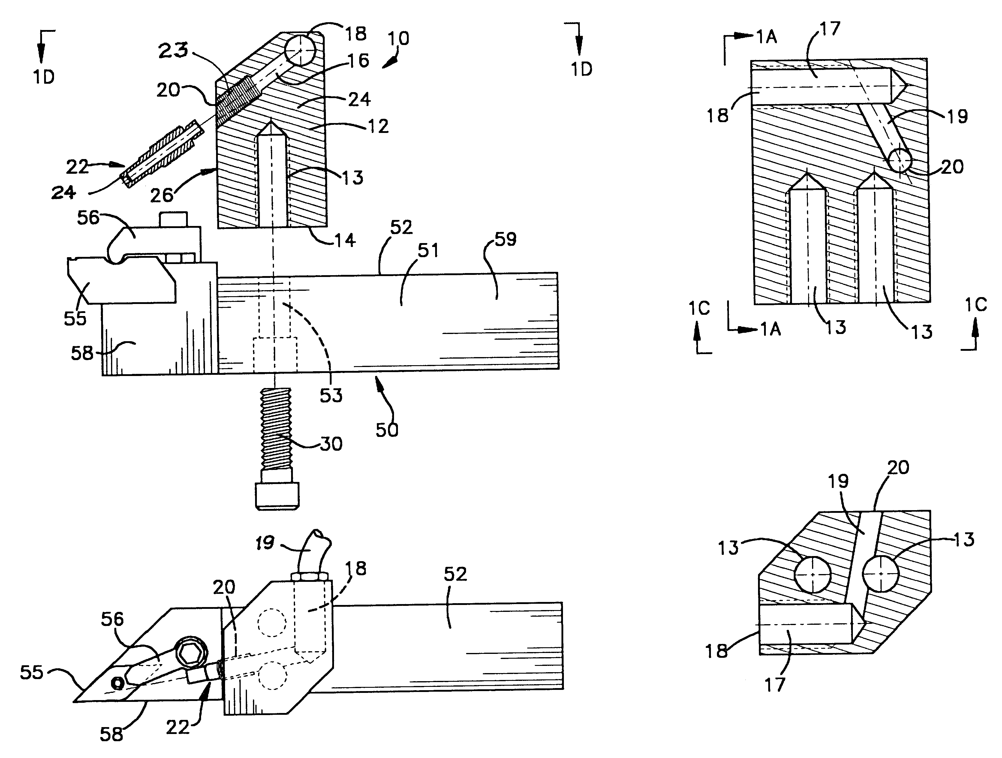
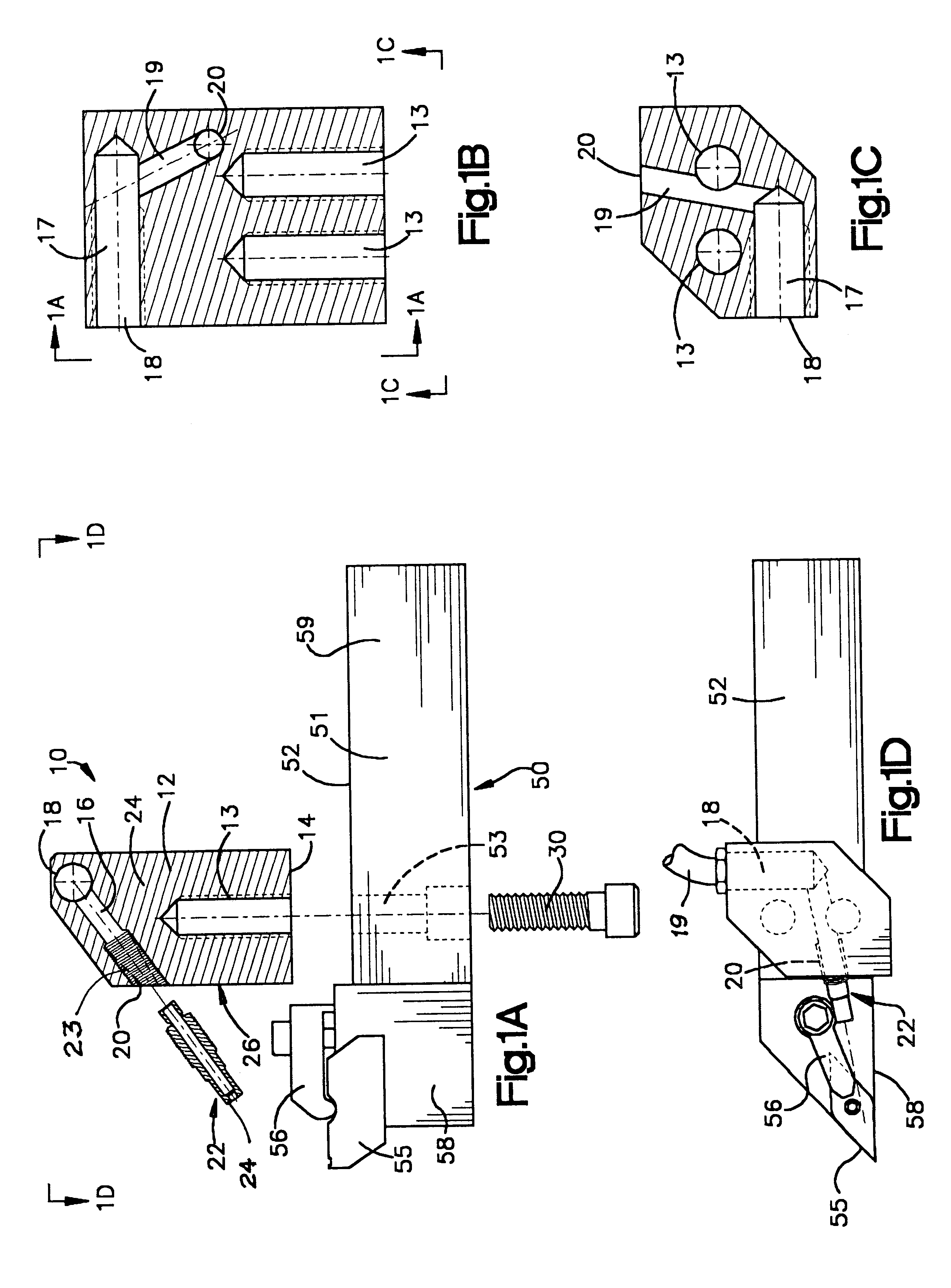
As shown in FIGS. 1A-1D, one particular embodiment of the invention includes a universal tool holder coolant delivery adapter, indicated generally at 10, which is configured for attachment to a tool holder 50. The adapter 10 includes a body 12 with a mounting surface 14. The tool holder 50 has a body 51 with at least one generally flat surface 52 with which the mounting surface 14 of the adapter 10 is placed in contact. One or more set screws 30 are threaded through the tool holder body 51 through bores 53, and into female threaded bores 13 in the adapter body 12 to securely, and removably, attach the adapter 10 to the tool holder 50. Although shown with bores 53 and 13 oriented generally orthogonally through the tool holder body 51 and adapter body 12, it is within the scope of the invention to alternatively orient the bores so that the adapted is attachable to the tool holder at various angles. Also, multiple mounting bores may be provided in both the tool holder and the adapter s...


PUM

PropertyMeasurementUnit
Angleaaaaaaaaaa
Angleaaaaaaaaaa
Flow rateaaaaaaaaaa

Abstract

Universal tool holder coolant delivery adapters have adapter bodies which are removably attachable to a tool holder by at least one fastening device, the adapter located between an attachment end of the tool holder and a distal end of the tool holder, the distal end of the tool holder having a cutting tool attached thereto, the adapter bodies having an internal coolant passageway including an intake port and an exit port, the intake port adapted for attachment to a pressurized coolant supply line and the outlet port adapted for attachment to or configured in the form of a coolant spray nozzle, the coolant spray nozzle being closely positioned and substantially aligned with the cutting interface of the cutting tool and a workpiece.

Description

The present invention is in the general field of machining and metal working and, more specifically, in the field of tools and systems for cutting and machining steel and metal.Machines that are designed for cutting metal or steel do so by applying various tools to a workpiece. In various types of turning operations, this can be done by having a rotating tool approach a fixed workpiece or by spinning the workpiece itself (such as a piece of bar stock) as the tool comes in contact from a certain angle. The moving contact of the tool with the stock produces a large amount of heat which must be dissipated to avoid destroying the tool. Most cutting machines are equipped with a coolant reservoir and a low pressure pump that sprays coolant over the entire machining process from hoses with diameters as large as one inch. The purpose is to flood the entire cutting process which, in theory, improves the tool life by minimizing the temperature increase. This approach has several flaws, one of...

Claims


Application Information

Patent Timeline
IPC IPC(8): B23Q11/10B23B27/00B23B27/10
CPCB23B27/10B23Q11/1084Y10S82/901Y10T82/16098Y10T407/2268Y10T407/14Y10T407/11
Inventor SLABE, BRENDAN
Owner SLABE MACHINE PROD
Learn More