
Eureka
For R&D, Eureka makes reading and utilizing patents & technical documents easy.
Eureka AIR
Designed for self-driven R&D workflows. Generate viable solutions, solve complex R&D challenges, empower your innovation with AI.

Eureka Materials
Designed for material experts only. Revolutionize your material R&D, from search, analyze, to developing new materials.

TechResearch
Generate reliable direction feasibility study reports for your R&D in just a few steps.

TechSeek
Discover and master advanced knowledge NOW. Basics, ideas, possibilities, all at once.

TechMind
As an expert in R&D Theories, TechMind can generates customized viable solutions instantly.

TechRisk
Analyze your overall solution with one click, know your potential R&D risks in advance.

TechMonitor
Get weekly tech updates, stay abreast of the latest tech innovations and key insights.
Integrated microsprings for speed switches
- Summary
- Abstract
- Description
- Claims
- Application Information
AI Technical Summary
Problems solved by technology
Method used
Image

Examples
Embodiment Construction
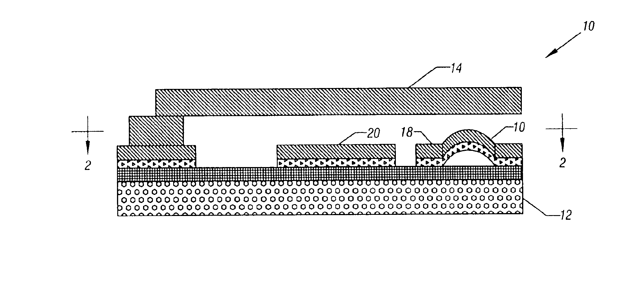
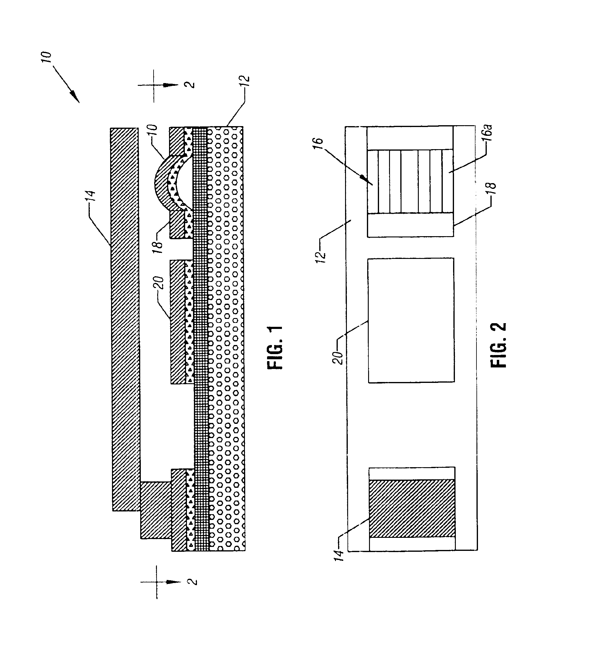
Referring to FIG. 1, an integrated microelectro-mechanical system (MEMS) switch 10 for a high speed circuit, such as a radio frequency circuit, includes a semiconductor structure 12 coupled to a contact arm 14. In one embodiment of the present invention, the contact arm 14 is a cantilevered contact arm. The free end of the contact arm 14 contacts a microspring dimple 16 positioned on the structure 12. The actuation or movement of the arm 14 may be under control of a plate 20 which applies an electrical force to the arm 14 to attract it towards the structure 12 in one embodiment of the present invention.
As shown in FIG. 2, the microspring dimple 16 may include a plurality of spaced hemispherical strips 16a which extend between contact areas 18 for electrical connection to the remainder of the controlled circuit. In some embodiments, the microspring dimple strips 16a may be made of relatively stiff material that is resilient so that it is possible to have a large contact area between ...
PUM
 Abstract
Description
Claims
Application Information
 - R&D Engineer
- R&D Manager
- IP Professional
- Industry Leading Data Capabilities
- Powerful AI technology
- Patent DNA Extraction
Browse by: Latest US Patents, China's latest patents, Technical Efficacy Thesaurus, Application Domain, Technology Topic, Popular Technical Reports.
© 2024 PatSnap. All rights reserved.Legal|Privacy policy|Modern Slavery Act Transparency Statement|Sitemap|About US| Contact US: help@patsnap.com