Multifrequency inverted-F antenna

a multi-frequency inverted-f antenna and antenna technology, applied in the field of antennas, can solve the problem that the inverted-f antenna cannot adjust the frequency bands through input and output impedance, and achieve the effect of reducing the impedance of the input and outpu

Inactive Publication Date: 2005-03-01
WISTRON NEWEB
View PDF7 Cites 137 Cited by
  • Summary
  • Abstract
  • Description
  • Claims
  • Application Information

AI Technical Summary

Benefits of technology

Therefore, it is an object of the present invention to provide a multifrequency inverted-F antenna that is capable of overcoming the aforementioned drawbacks of the prior art.

Problems solved by technology

However, the latter (built-in type) are more attractive due to a tendency of folding and breaking associated with the former upon use.
Moreover, adjustment of the frequency bands through the input and output impedance is not possible for the conventional inverted-F antennas due to the fixed location of the signal feeding element 14 on the radiating element 11.

Method used


Image

  • Multifrequency inverted-F antenna
  • Multifrequency inverted-F antenna
  • Multifrequency inverted-F antenna

Examples


Embodiment Construction

For the sake of brevity, like elements are denoted by the same reference numerals throughout the disclosure.

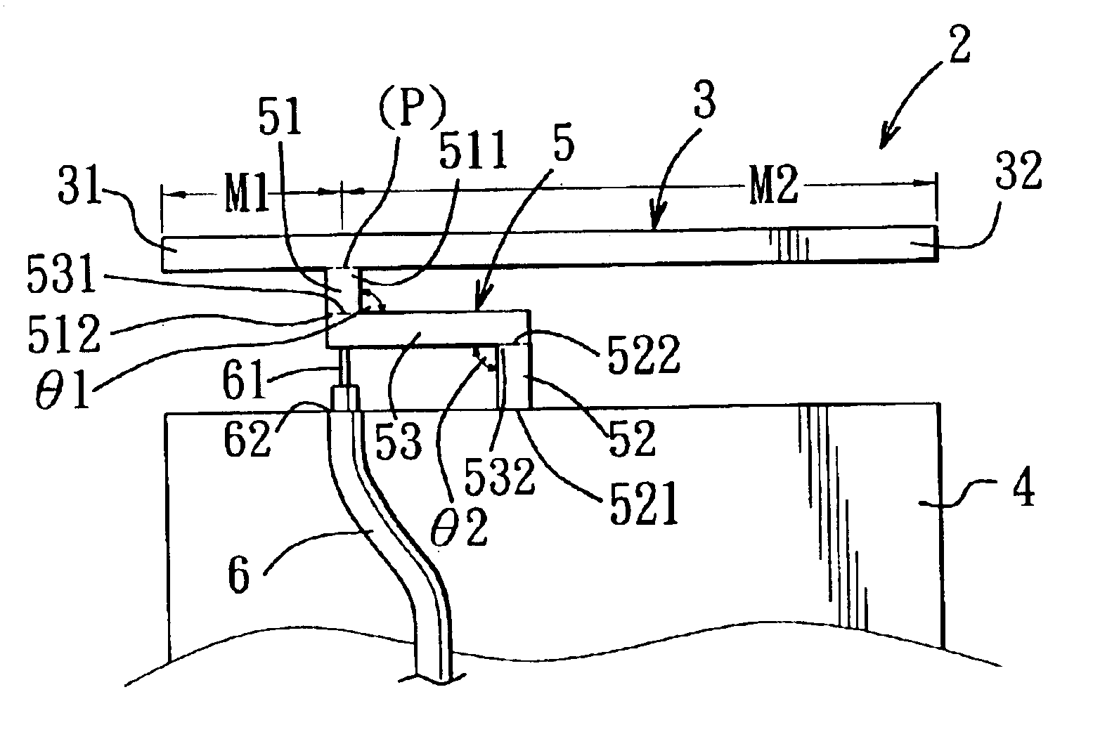
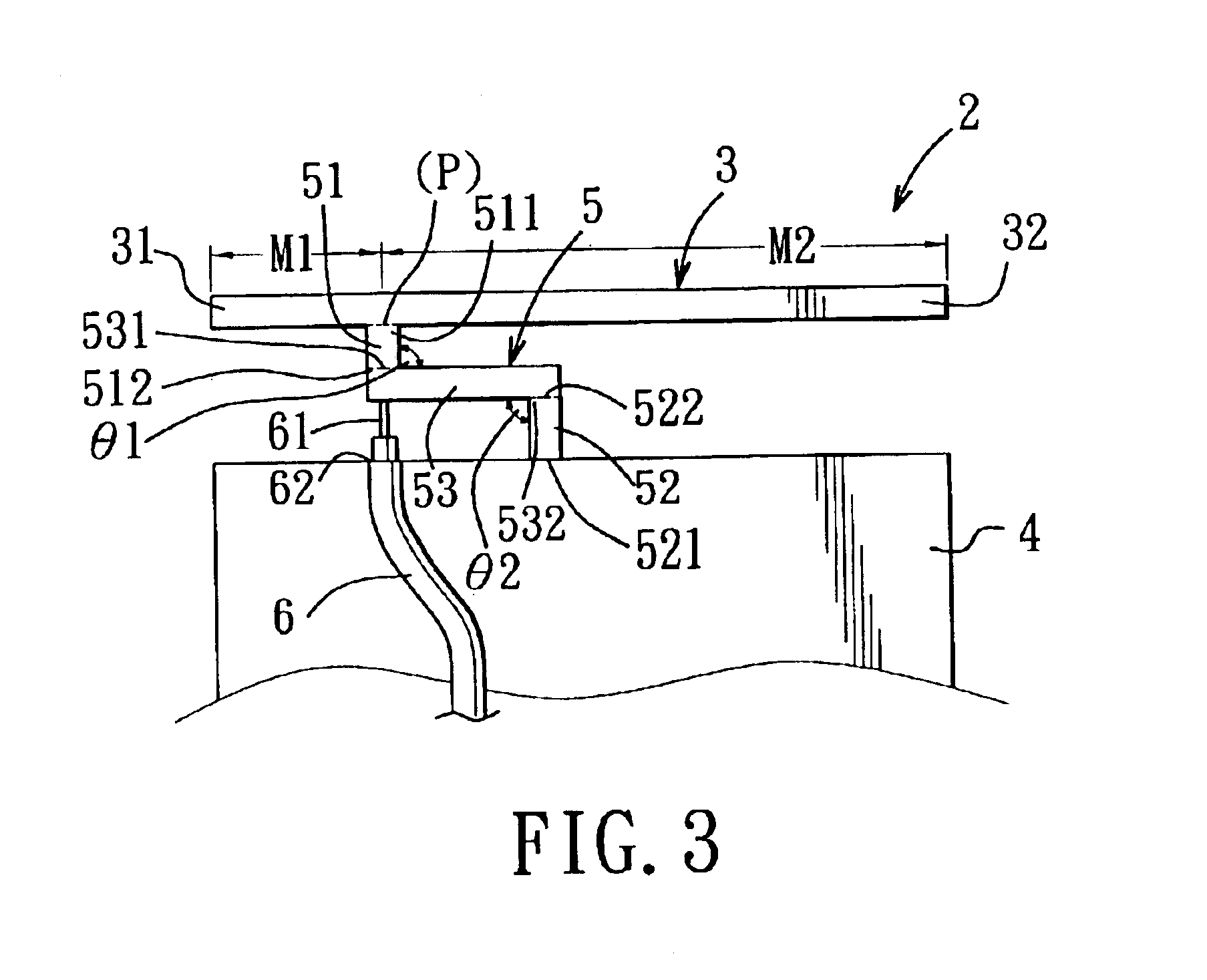
FIGS. 3 to 5 illustrate a first preferred embodiment of a multifrequency inverted-F antenna 2 of this invention. The antenna 2 includes: a conductive radiating element 3 in the form of a wire that extends in a longitudinal direction and that has opposite first and second ends 31, 32 lying in the longitudinal direction; a conductive grounding element 4 spaced apart from the radiating element 3 in a transverse direction relative to the longitudinal direction; a conductive interconnecting element 5 extending between the radiating and grounding elements 3, 4 and including first, second, and third parts 51, 52, 53, the first part 51 being electrically connected to the radiating element 3 at a feeding point (P) between the first and second ends 31, 32 of the radiating element 3, the second part 52 being offset from the first part 51 in the longitudinal direction and being electrical...


PUM


Abstract

A multifrequency inverted-F antenna includes a radiating element having opposite first and second ends, a grounding element spaced apart from the radiating element, and an interconnecting element extending between the radiating and grounding elements and including first, second, and third parts. The first part is connected to the radiating element at a feeding point between the first and second ends. The second part is offset from the first part in a longitudinal direction, and is connected to the grounding element. The third part interconnects the first and second parts. A feeding line is connected to the interconnecting element.

Description

CROSS-REFERENCE TO RELATED APPLICATIONThis application claims priority of Taiwan patent Application No. 091123215, filed on Oct. 8, 2002.BACKGROUND OF THE INVENTION1. Field of the InventionThis invention relates to an antenna, more particularly to a multifrequency inverted-F antenna for a portable electronic device.2. Description of the Related ArtWireless communication devices, such as cellular phones, notebook computers, electronic appliances, and the like, are normally installed with an antenna that serves as a medium for transmission and reception of electromagnetic signals. The antenna can be built outside or inside the devices. However, the latter (built-in type) are more attractive due to a tendency of folding and breaking associated with the former upon use.FIG. 1 illustrates a conventional multifrequency Planar Inverted-F Antenna (PIFA) which includes a rectangular conductive radiating element 11 having opposite left and right ends, a rectangular conductive grounding elemen...

Claims


Application Information

Patent Timeline
Patent Type & Authority Patents(United States)
IPC IPC(8): H01Q1/22H01Q5/00H01Q9/04H01Q1/24H01Q5/371
CPCG06F1/1616G06F1/1698H01Q1/22H01Q1/2266H01Q5/371H01Q9/0421H01Q9/045H01Q9/42H01Q1/241
Inventor FANG, CHIEN-HSINGCHANG, YUAN-LILIN, HUEY-JEN
Owner WISTRON NEWEB
Why Eureka
Try Eureka