Above sheathing ventilation system

a ventilation system and above-sheathing technology, applied in ventilation systems, lighting and heating apparatus, heating types, etc., can solve the problems of increasing the severity and scope of wildfires, reducing the incidence of mold and dry rot, and building exposure to wildfires

Active Publication Date: 2014-07-22
ODANIELS LLC
View PDF177 Cites 34 Cited by
  • Summary
  • Abstract
  • Description
  • Claims
  • Application Information

AI Technical Summary

Benefits of technology

[0010]In accordance with yet another embodiment, a vented eave riser comprises a barrier wall and an ember impedance structure positioned proximate to the barrier wall. The barrier wall is adapted to fit between a roof deck and a layer of roof cover elements of a roof. The barrier wall comprises one or more openings permitting air flow through the barrier wall. The ember impedance structure substantially prevents ingress of floating embers through the ember impedance structure, while permitting air flow through the ember impedance structure.

Problems solved by technology

In addition, increased ventilation in an attic space tends to reduce the humidity within the attic, which can prolong the life of lumber used in the building's framing and elsewhere by diminishing the incidence of mold and dry-rot.
In many areas, buildings are at risk of exposure to wildfires.
These embers can travel, airborne, up to one mile or more from the initial location of the wildfire, which increases the severity and scope of the wildfire.
One way wildfires can damage buildings is when embers from the fire land either on or near a building.
Likewise, burning structures produce embers, which can also travel along air currents to locations removed from the burning structures and pose hazards similar to embers from wildfires.
Embers that enter the structure can encounter combustible materials and set fire to the building.
Fires also generate flames, which can likewise set fire to or otherwise damage buildings when they enter the building's interior through vents.

Method used


Image

  • Above sheathing ventilation system
  • Above sheathing ventilation system
  • Above sheathing ventilation system

Examples


Embodiment Construction

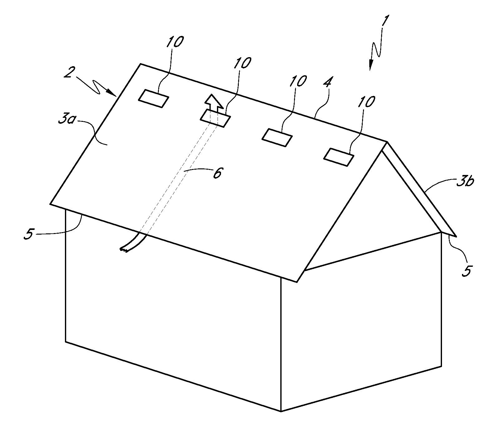
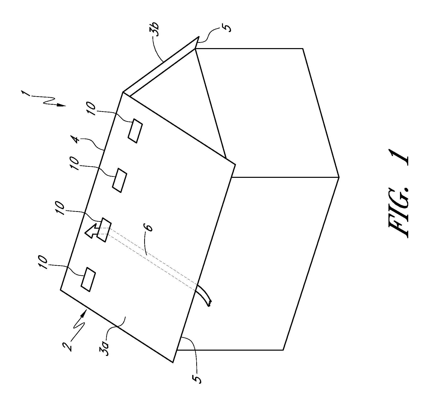
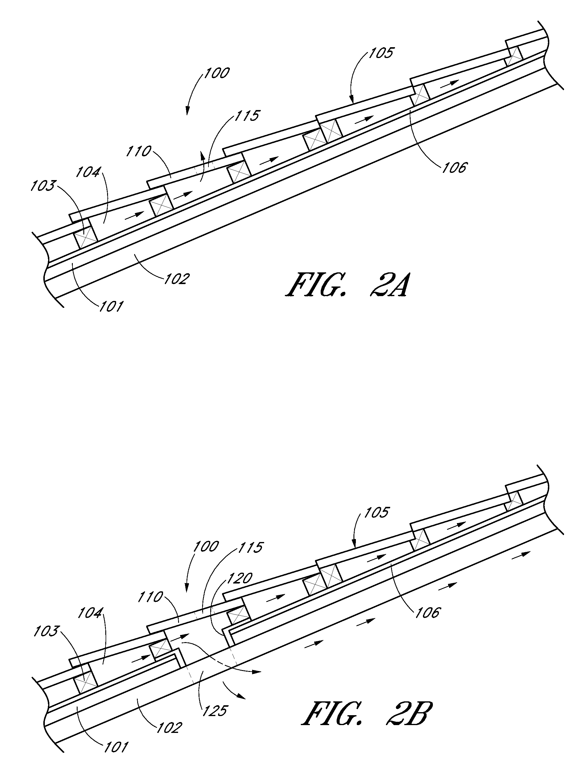
[0037]FIG. 1 shows a building 1 with a roof 2 comprising two fields 3a and 3b that are joined at their upper ends to define a ridge 4. Lower edges 5 of the fields are referred to as “eaves.” The fields 3a and 3b typically comprise a sheathing or roof deck covered with a layer of roof cover elements 105 (FIGS. 2A and 2B), such as tiles (e.g., clay, metal, or concrete), shingles (e.g., wooden, clay, asphalt, or composition), or sheeting (e.g., metal). The sheathing is typically supported by rafters (not shown). The illustrated roof is suitable for having one or more vent members 10 according to one embodiment of the invention. Also, skilled artisans will appreciate that the vent members 10 may be provided in a wide variety of different types of roofs, including those not having ridges or sloped fields.

[0038]The roof cover elements 105 and / or the vent members 10 may be supported by a series of battens to create additional airspace beneath the roof cover elements 105 and / or vent members...


PUM


Abstract

A roof structure and a vented eave riser are described. A vented eave riser can include a barrier wall with one or more air flow openings, and an ember impedance structure positioned proximate to the barrier wall. A roof structure may comprise a roof deck and a layer of roof cover elements spaced above the roof deck to form an air layer between the roof deck and the roof cover elements. The roof structure may also comprise one or more vent members each replacing and mimicking an appearance of one or more roof cover elements of the layer of roof cover elements, and / or at least one vented eave riser positioned at an eave between the roof deck and the layer of roof cover elements. The vent members and / or the vented eave riser may further include an ember impedance structure, such as a fire-resistant mesh material or a baffle structure.

Description

PRIORITY CLAIM[0001]This application claims the benefit under 35 U.S.C. §119(e) of U.S. Provisional Patent Application No. 61 / 386,886 filed Sep. 27, 2010, which is hereby incorporated by reference in its entirety.BACKGROUND OF THE INVENTION[0002]1. Field of the Invention[0003]The present disclosure relates to ventilation systems, and more particularly to so-called Above Sheathing Ventilation (ASV) systems.[0004]2. Description of the Related Art[0005]Ventilation of a building has numerous benefits for both the building and its occupants. For example, ventilation of an attic space can prevent the attic's temperature from rising to undesirable levels, which also reduces the cost of cooling the interior living space of the building. In addition, increased ventilation in an attic space tends to reduce the humidity within the attic, which can prolong the life of lumber used in the building's framing and elsewhere by diminishing the incidence of mold and dry-rot. Moreover, ventilation prom...

Claims


Application Information

Patent Timeline
Patent Type & Authority Patents(United States)
IPC IPC(8): E04D13/17
CPCF24F7/02E04B1/94E04H9/14E04D1/30E04D13/17E04D13/178E04D2001/309E04B1/70
Inventor DANIELS, GREGORY, S.
Owner ODANIELS LLC
Why Eureka
Try Eureka