Radar system and method for virtual antenna signals

a virtual antenna and antenna technology, applied in the field of radar systems with antenna arrays, can solve the problems of compounding the error in measuring the phase difference of detected signals from narrow spaced antenna elements

Active Publication Date: 2016-03-31
APTIV TECH LTD
View PDF1 Cites 40 Cited by
  • Summary
  • Abstract
  • Description
  • Claims
  • Application Information

AI Technical Summary

Problems solved by technology

Any error in measuring the phase difference of detected signals from the narrow spaced antenna elements is compounded when that error is applied to the virtual phase difference.

Method used


Image

  • Radar system and method for virtual antenna signals
  • Radar system and method for virtual antenna signals
  • Radar system and method for virtual antenna signals

Examples


Embodiment Construction

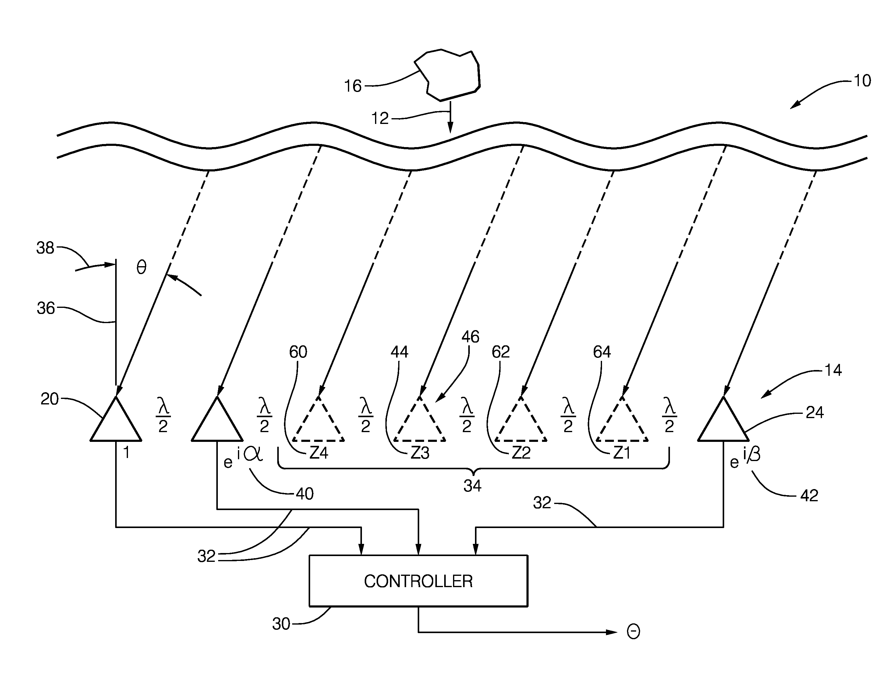
[0011]FIG. 1 illustrates a non-limiting example of a radar system, hereafter referred to as the system 10. The system 10 is generally configured to process a reflected signal 12 detected by a radar antenna, hereafter the antenna 14. While not shown, it will be understood by those in the art that the reflected signal 12 is the result of a target 16 reflecting a transmitted signal (not show) emitted by a transmit antenna (not shown) that may be part of the system 10, as will be recognized by those in the art. A suitable frequency for the reflected signal 12 is 76.5* 10̂9 Hertz (76.5 GHz), so an example wavelength of 2.6 millimeters (mm) will be used for the discussion that follows. The examples presented herein are non-limiting as those skilled in the art will recognize that dimensions of the antenna 14 can be scaled or otherwise altered to adapt the antenna 14 for operation at a different radar frequency.

[0012]The antenna 14 includes a reference element 20, and an alpha element 22 sp...


PUM


Abstract

A radar system includes a radar antenna and a controller. The antenna includes a reference element, an alpha element spaced apart from the reference element by one half-wavelength of the reflected signal, and a beta element spaced apart from the reference element by an even number of half-wavelengths of the reflected signal. The controller is configured to determine an alpha phase difference between detected signals from the reference element and the alpha element, determine a beta phase difference between detected signals from the reference element and the beta element, and determine a first virtual phase difference that corresponds to the reflected signal expected to be detected by a first virtual element located halfway between the reference element and the beta element. The first virtual phase difference is based on the beta phase difference divided by two.

Description

TECHNICAL FIELD OF INVENTION[0001]This disclosure generally relates to radar systems with antenna arrays, and more particularly relates to beam-forming using synthesized signals of virtual antenna elements from signals received from actual antenna elements.BACKGROUND OF INVENTION[0002]Radar receive-antenna arrays with two closely spaced elements (e.g. spaced apart one half-wavelength) and one widely spaced element (e.g. spaced apart multiple wavelengths) have been proposed. The reflected signals detected by each antenna element may be used to synthesize or determine a virtual phase difference that corresponds to the reflected signal expected to be detected by a virtual element located between the two closely spaced antenna elements and the widely spaced antenna element. Phase comparison mono-pulse (PCMP) uses a phase difference of detected signals from the narrow spaced antenna elements to estimate a virtual phase difference for a virtual element based on the separation or spacing o...

Claims


Application Information

Patent Timeline
Patent Type & Authority Applications(United States)
IPC IPC(8): G01S7/02G01S13/931
CPCG01S7/02G01S7/41G01S13/4454G01S13/931
Inventor ALCALDE, CARLOS, A.
Owner APTIV TECH LTD
Why Eureka
Try Eureka