Fluid conduit for use with hydraulic actuator

a fluid conduit and actuator technology, applied in the field of fluid conduits, can solve the problems of undesirable power loss, elastic expansion and contraction of the flexible hose carrying fluid to or from the actuator, and the expansion of the diameter of the flexible hose with increasing fluid pressure,

Inactive Publication Date: 2005-03-08
GENERAL DYNAMICS ADVANCED INFORMATION SYSTEMS
View PDF35 Cites 12 Cited by
  • Summary
  • Abstract
  • Description
  • Claims
  • Application Information

AI Technical Summary

Benefits of technology

Further according to the present invention, a fluid line is provided for use in an active control device for controlling a rotor blade, or a pivoting flap on the rotor blade, of a rotary wing aircraft having an airframe and a rotor rotatable relative to the airframe. The rotor includes a hub and at least one elongated rotor blade connected at one end to the hub and extending radially outwardly from the hub such that when the rotor hub is rotatably driven the rotor blade rotates with the hub. The rotor blade is movable about a pitch axis extending along its length and about the two transverse axes. A hydraulic actuation system is provided for moving the blade or flap about the pitch axis including a fluid source, means for controlling the position of the blade or flap about the axis, and a hydraulic actuator operatively connected to the blade or flap for changing the position of the blade or flap about the axis in response to a signal from the controlling means. The fluid line comprises a rigid tubular member formed in the shape of a helix of at least 2 revolutions and a non-constant pitch length. The ends of the tube are adapted to be sealingly connected between the fluid source and t

Problems solved by technology

However, because the wall stiffness of the flexible hose is low (allowing the hose to be flexible to motion), the flexible hose expands in diameter with increased fluid pressure.
In high performance hydraulic actuator systems, the elastic expansion and contraction of a flexible hose carrying fluid to or from the actuator consumes power which would otherwise be transmitted to the actuator.
Given that there is a desire to keep the fluid source as small as possible, this power loss is undesirable.
Moreover, the lapse time between a control signal commanding the fluid source to supply or remove flu

Method used


Image

  • Fluid conduit for use with hydraulic actuator
  • Fluid conduit for use with hydraulic actuator
  • Fluid conduit for use with hydraulic actuator

Examples


Embodiment Construction

Certain terminology is used herein for convenience only and is not to be taken as a limitation on the invention. For example, words such as “upper,”“lower,”“left,”“right,”“horizontal,”“vertical,”“upward,” and “downward” merely describe the configuration shown in the Figures. Indeed, the components may be oriented in any direction and the terminology, therefore, should be understood as encompassing such variations unless specified otherwise.

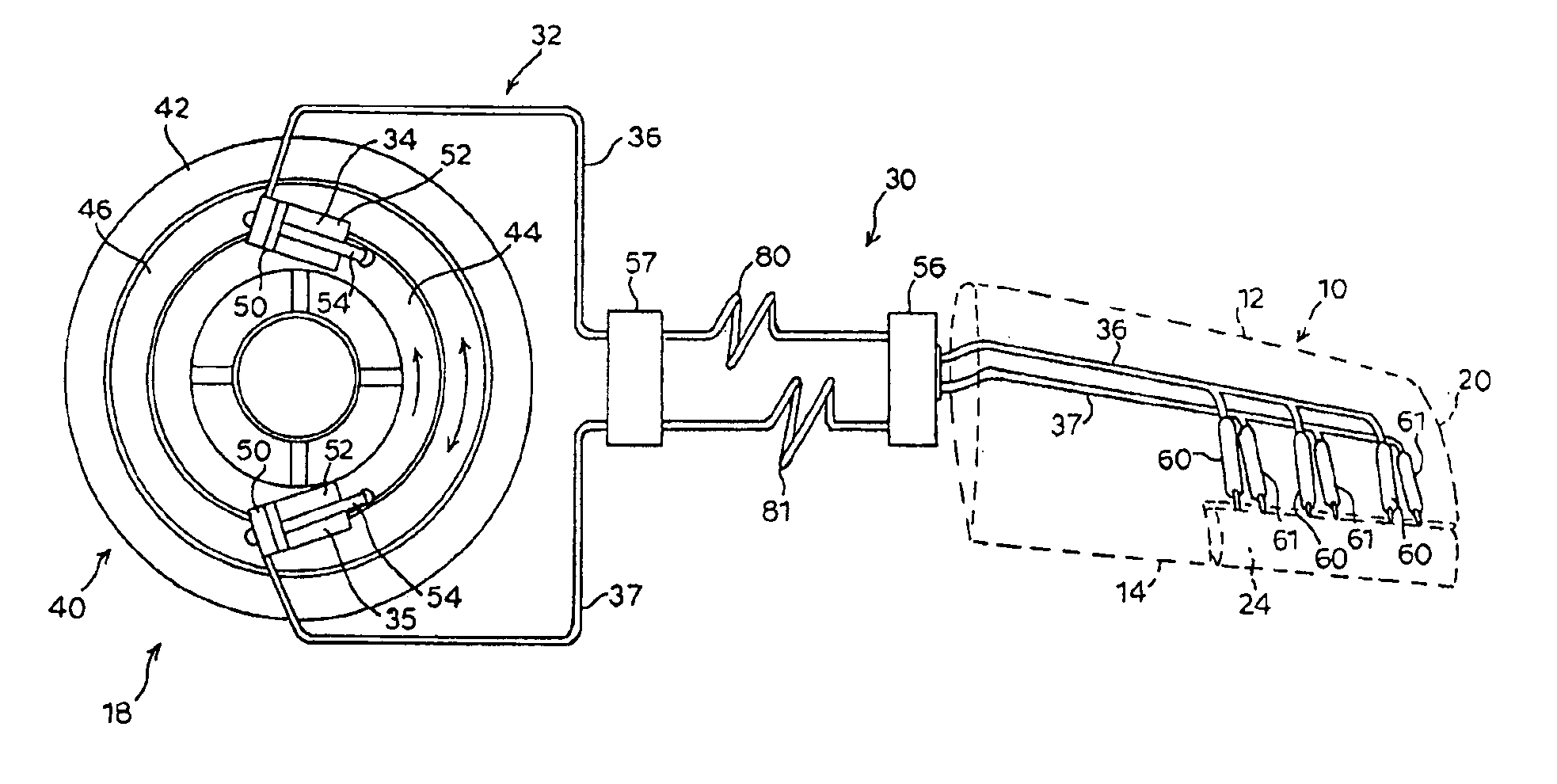
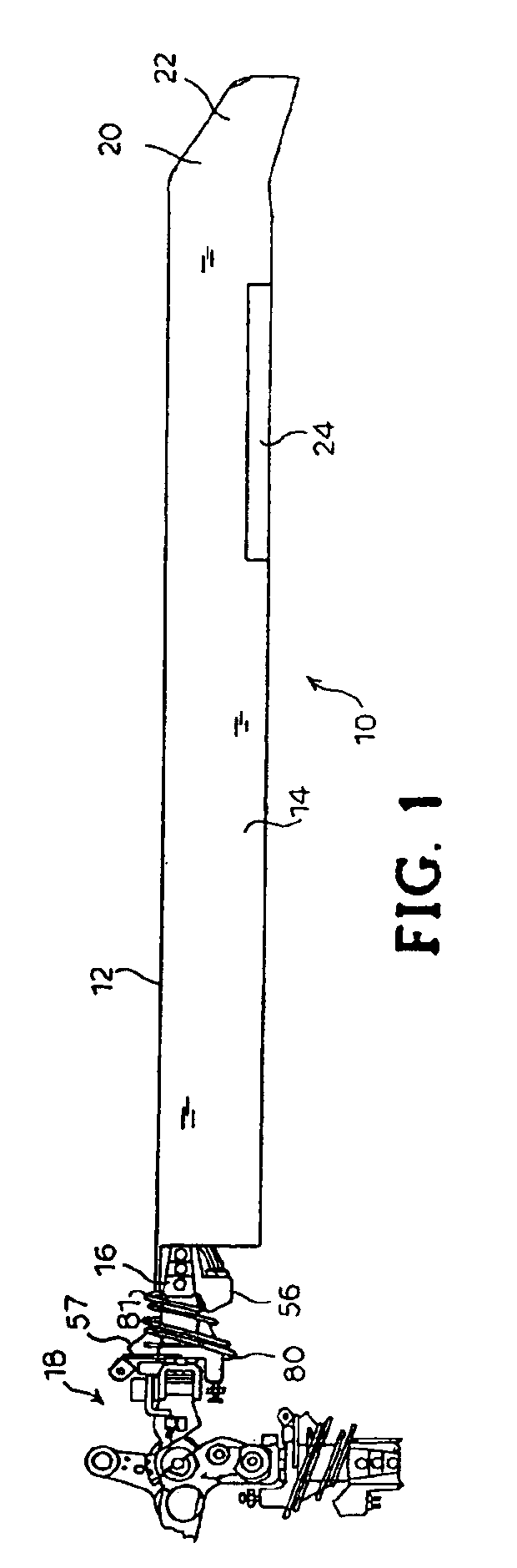
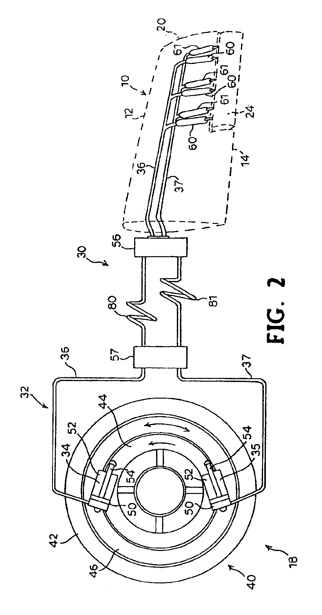
The present invention is illustrated and described as it is contemplated for use in a hydraulic actuation system on a helicopter rotor blade for providing active control of the blade or one or more flaps on the blade. However, it should be understood that the present invention is not limited to such an embodiment. For example, the present invention can be used in hydraulic blade or flap pitch control systems in various types of rotating machines, devices and instrumentalities such as, for example, a fan blade, a propeller or airscrew on a propelle...


PUM


Abstract

A fluid conduit is provided for use in a hydraulic actuating system for controlling an instrumentality disposed on a rotating portion of a machine. The fluid conduit transports pressurized fluid between a fluid source disposed on a non-rotating portion of the machine and the instrumentality and comprises a rigid tubular member formed in the shape of a helix having at least about 2 revolutions and a non-constant pitch length. The ends of the tube are adapted to be sealingly connected between the fluid source and the instrumentality. The fluid conduit is used, for example, in an apparatus and system for controlling a hydraulic actuator mounted on a rotating blade.

Description

BACKGROUND OF INVENTIONThis invention relates generally to a fluid conduit, and more particularly to a flexible fluid conduit for transporting a pressurized fluid between a fluid source and an actuator mounted on, for example, an articulated portion of a machine such as a rotor blade on a rotary wing aircraft.Fundamental to the operation of many machines, devices, or instrumentalities is the ability to control an articulated part which moves relative to the rest of the instrumentality, device or machine. For example, many turbine or fan devices have facility for dynamically controlling the pitch of their rotor blades. Pitch is a factor in determining the dynamic forces acting on the blade and, hence, determining the forces applied by the blades to the frame of the instrumentality.Control of blade pitch generally originates in the frame of the instrumentality which is stationary relative to the articulated portion of the instrumentality. Control of the variable pitch of the blades of...

Claims


Application Information

Patent Timeline
IPC IPC(8): B64C27/00B64C27/615B64C27/605
CPCB64C27/615B64C27/605B64C2027/7266Y10S414/131Y02T50/34Y02T50/30
Inventor TERPAY, GREGORY W.
Owner GENERAL DYNAMICS ADVANCED INFORMATION SYSTEMS
Why Eureka
Try Eureka