

Unidirectional motion asymmetric damped tensioner
a technology of asymmetric damping and tensioner, which is applied in the direction of mechanical equipment, belts/chains/gearrings, and belts. it can solve the problems of tensioner lock-up and belt slippage, the inability of the twisting spring, and the need for asymmetric damping
- Summary
- Abstract
- Description
- Claims
- Application Information
AI Technical Summary
Benefits of technology
Problems solved by technology
Method used
Image

Examples
Embodiment Construction
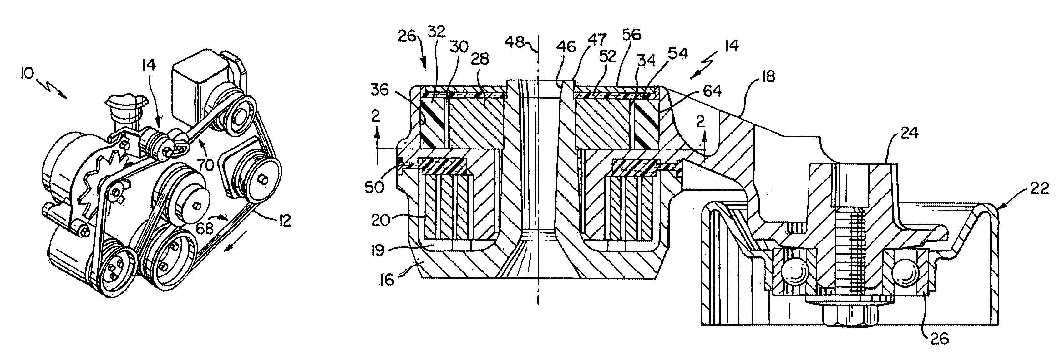
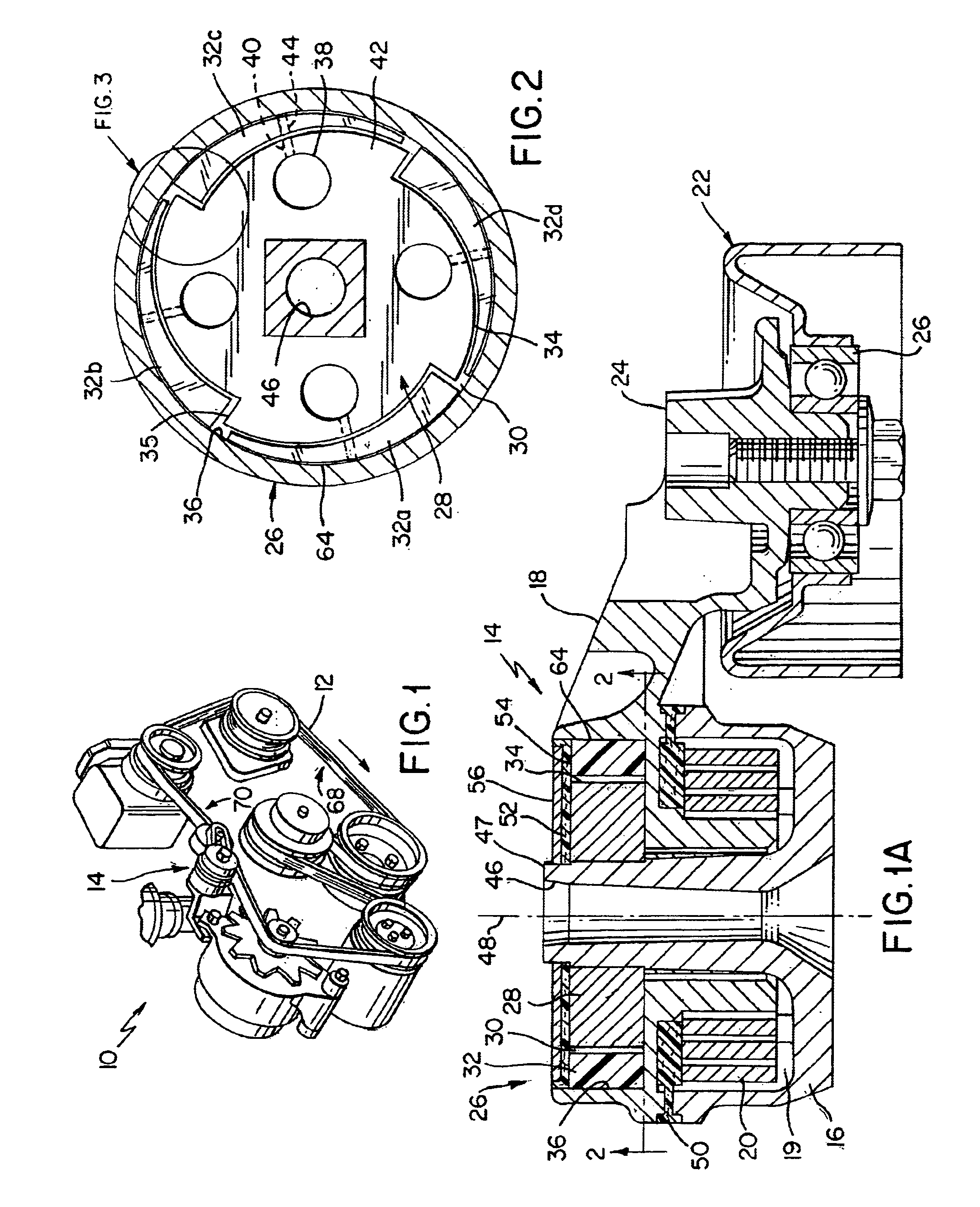
This embodiments relate to a new method and apparatus for a belt tensioner.
BACKGROUND
Many automobile engines currently on the market utilize an endless power transmission belt for driving a plurality of driven accessories. They employ a tensioning system utilized to provide a tensioning force on the endless power transmission belt, which may be of any suitable type known in the art. Preferably, the belt is made primarily of a polymeric, Kevlar or Aramid material because the unique features of the tensioner of this invention readily permit the tensioner to tension a belt having a polyester load-carrying cord in an efficient manner.
In many of these automotive accessory drives it is necessary to provide a correct tension to control a tension ratio throughout the life of the belt. With the advent of the single belt V-ribbed drive system, this is of increasing importance since belts are longer and some accessories are driven off the backside of the belt as a flat belt drive. Automatic te...
PUM
 Abstract
Description
Claims
Application Information