
Printing device for installing GEM electrical outlet box

a printing device and electrical outlet box technology, applied in the direction of mechanical measuring arrangement, manufacturing tools, instruments, etc., can solve the problems of electrical outlet box generally not providing a clean fit, requiring additional time and effort by the electrician,

Inactive Publication Date: 2005-03-15
GEM TEMP
View PDF29 Cites 18 Cited by
  • Summary
  • Abstract
  • Description
  • Claims
  • Application Information

AI Technical Summary

Benefits of technology

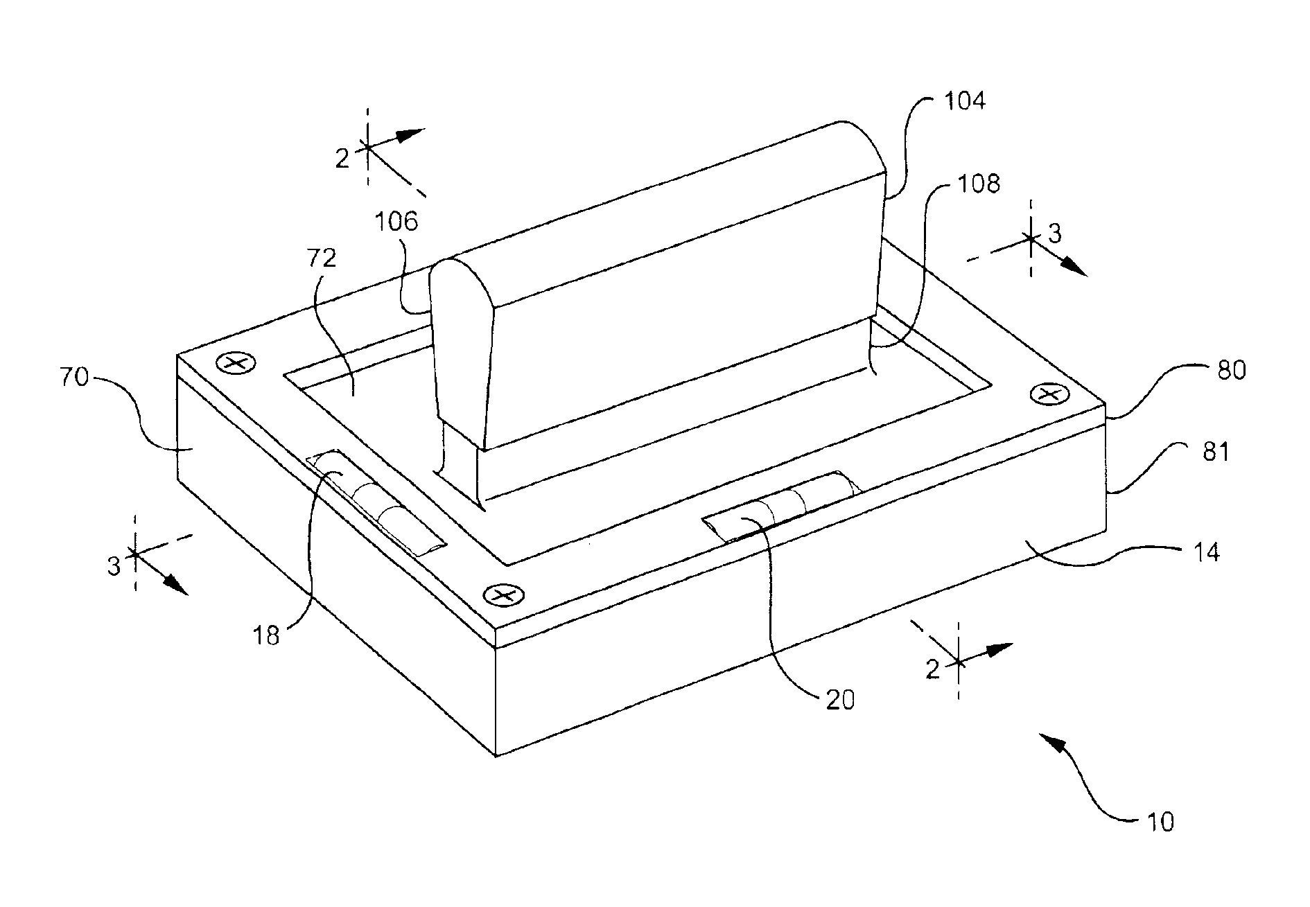
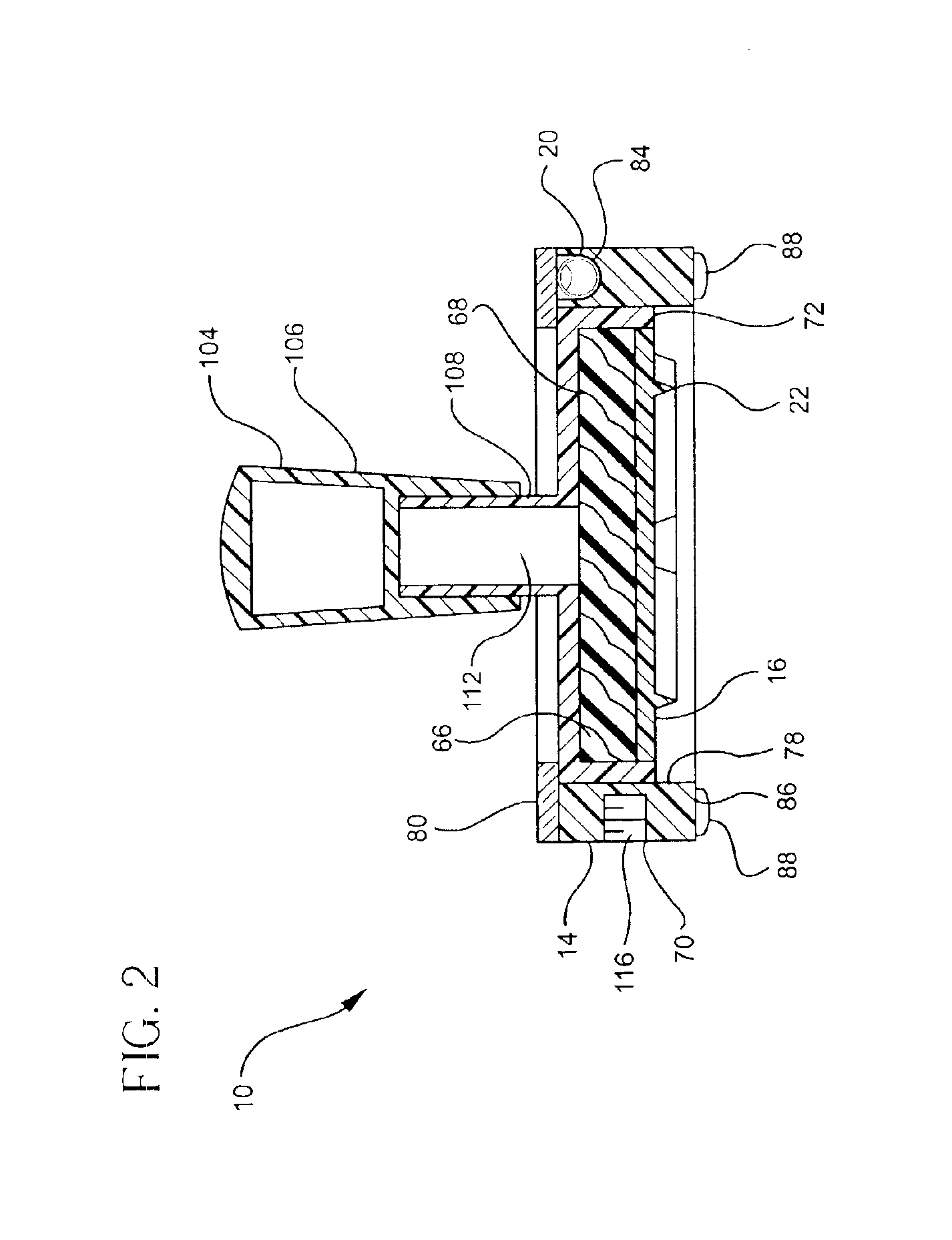
The present invention is a printing device for marking an outline of an opening to be cut in a wall for installing a GEM electrical outlet box in the wall. The printing device includes a housing, a stamp body, and at least a first level. The stamp body is connected to the housing and has a face configured to print the outline for cutting the opening in the wall. The first level is attached to the housing. Preferably the housing includes a frame, a piston body, and a spring assembly. The frame is formed with an opening defined by a boundary and includes a stop. The frame has a base for initial placement of the housing against the wall prior to printing the outline. The piston body supports the stamp body and has a shape formed to cooperate with the boundary so that the piston body can be reciprocated within the opening. The spring assembly is configured to bias the piston body against the stop in the absence of pressure and to allow the piston body to translate towards the base for printing the outline when pressure is applied to the piston body. The first level can be attached to either the frame or the piston body.

Problems solved by technology

The openings that result through the practice of tracing the electrical outlet box generally do not provide a clean fit and generally must be trimmed further to accommodate the electrical outlet box.
This requires additional time and effort by the electrician.

Method used


Image

  • Printing device for installing GEM electrical outlet box
  • Printing device for installing GEM electrical outlet box
  • Printing device for installing GEM electrical outlet box

Examples


Embodiment Construction

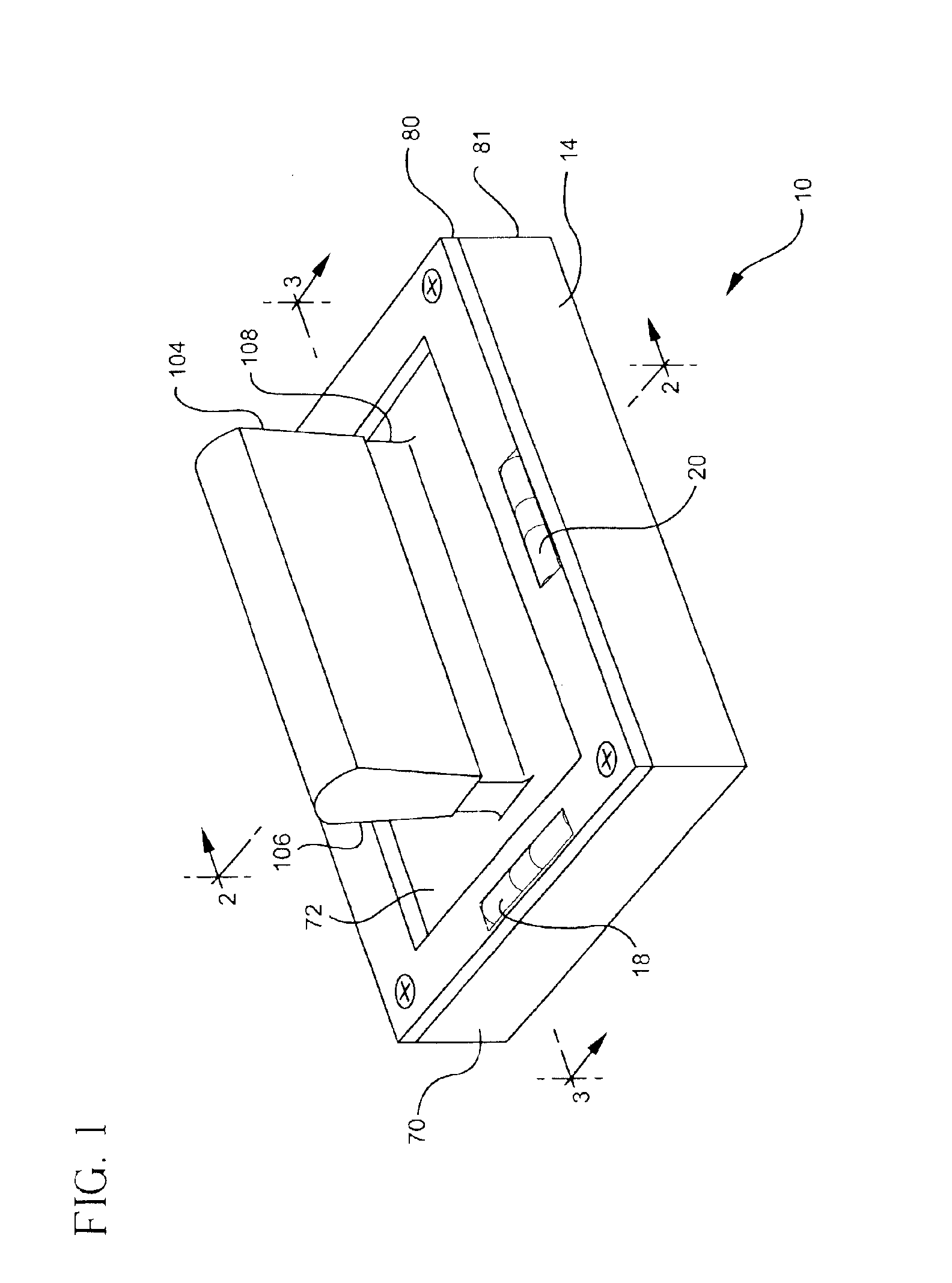
Referring initially to FIG. 1, the present invention is a printing device 10 for marking an outline 12 of an opening to be cut in a wall for installing a GEM electrical outlet box in the wall. As used herein, the terms “GEM electrical outlet box” refers to an electrical outlet box that is used for remodeling work and alterations where the sheetrock (drywall) or plaster are already installed. That is, the installation of a “GEM electrical outlet box” contemplates that the opening will be cut into an existing wall.

Referring to FIGS. 1, 2, and 4, the printing device 10 generally includes a housing 14, a stamp body 16, and at least one level 18, 20. The stamp body 16 has a face 22 configured to print the outline 12 for cutting the opening in the wall. The housing 14 is preferably configured to carry the stamp body 16 for actuation between a first holding position wherein the stamp body 16 is retained for arrangement against the wall without marking the wall, and second marking position ...


PUM


Abstract

The present invention is a device for printing an outline of an opening to be cut in a wall to facilitate the installation of a GEM electrical box in the wall. The outline is substantially rectangular having a first and second set of sides. The first set of sides is shorter than the second set of sides and includes a semi-oval portion located at the middle of each side. The second set of sides have a semi-oval portion located at the end of each side. The device includes a rubberstamp configured to print the outline on the wall, and also includes a handle and a pair of levels for locating (leveling) the device prior to imprinting the outline on the wall. The rubberstamp can includes an inking means for replenishing ink to the rubberstamp. The device can also include a spring assembly so that the rubberstamp can initially be located at a position on the wall without imprinting the outline on the wall, but will print the outline on the wall upon the application of pressure to the rubberstamp.

Description

BACKGROUND OF THE INVENTIONThe present invention relates generally to a printing device. More particularly, the present invention is directed to a printing device for marking an outline of an opening to be cut in a wall for installing a GEM electrical outlet box in the wall.The installation of an electrical outlet box in an existing wall generally requires an electrician to hold the box against the wall while leveling the box with a level to trace the exterior perimeter of the electrical outlet box on the wall. The electrician then cuts the opening in the wall based upon the tracing of the electrical outlet box. The openings that result through the practice of tracing the electrical outlet box generally do not provide a clean fit and generally must be trimmed further to accommodate the electrical outlet box. This requires additional time and effort by the electrician.Accordingly, devices have been developed for facilitating the marking of an outline for cutting an opening to install...

Claims


Application Information

Patent Timeline
Patent Type & Authority Patents(United States)
IPC IPC(8): G01B5/00G01D21/00B25H7/04B41K1/06H02G1/00H02G3/00
CPCB25H7/04B41K1/06H02G3/00H02G1/00H02G2200/30Y10S33/10
Inventor MELITTAS, WILLIAM
Owner GEM TEMP
Learn More