Seaplane with retractable twin floats

a technology of twin floats and seaplanes, applied in seaplanes, floats, transportation and packaging, etc., can solve the problems of simply not being aerodynamically efficient, and achieve the effect of sufficient buoyancy and stability

Inactive Publication Date: 2005-03-15
TIGERFISH AVIATION PTY LTD
View PDF15 Cites 12 Cited by
  • Summary
  • Abstract
  • Description
  • Claims
  • Application Information

AI Technical Summary

Benefits of technology

In one form of this invention, there is proposed a twin float aircraft with its floats arranged to at least substantially support the aircraft in a floating on water status providing sufficient buoyancy and stability for the aircraft during take off and landing, the aircraft having a first of the floats located to one side of a main fuselage of the aircraft, and a second of the floats located to a second side of the main fuselage which is opposite to the said first side of the main fuse

Problems solved by technology

A main current issue is that having floats in this

Method used


Image

  • Seaplane with retractable twin floats
  • Seaplane with retractable twin floats
  • Seaplane with retractable twin floats

Examples


Embodiment Construction

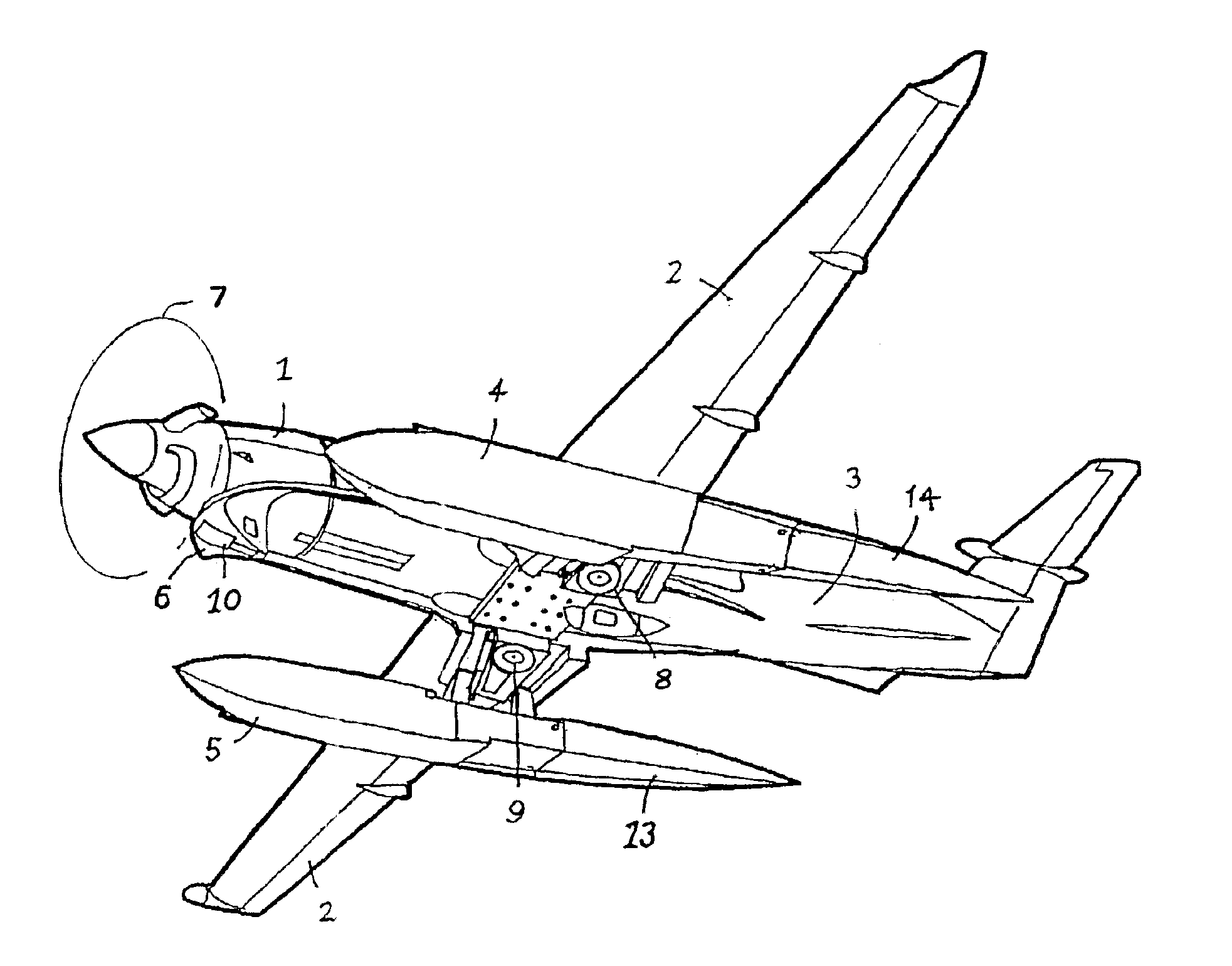
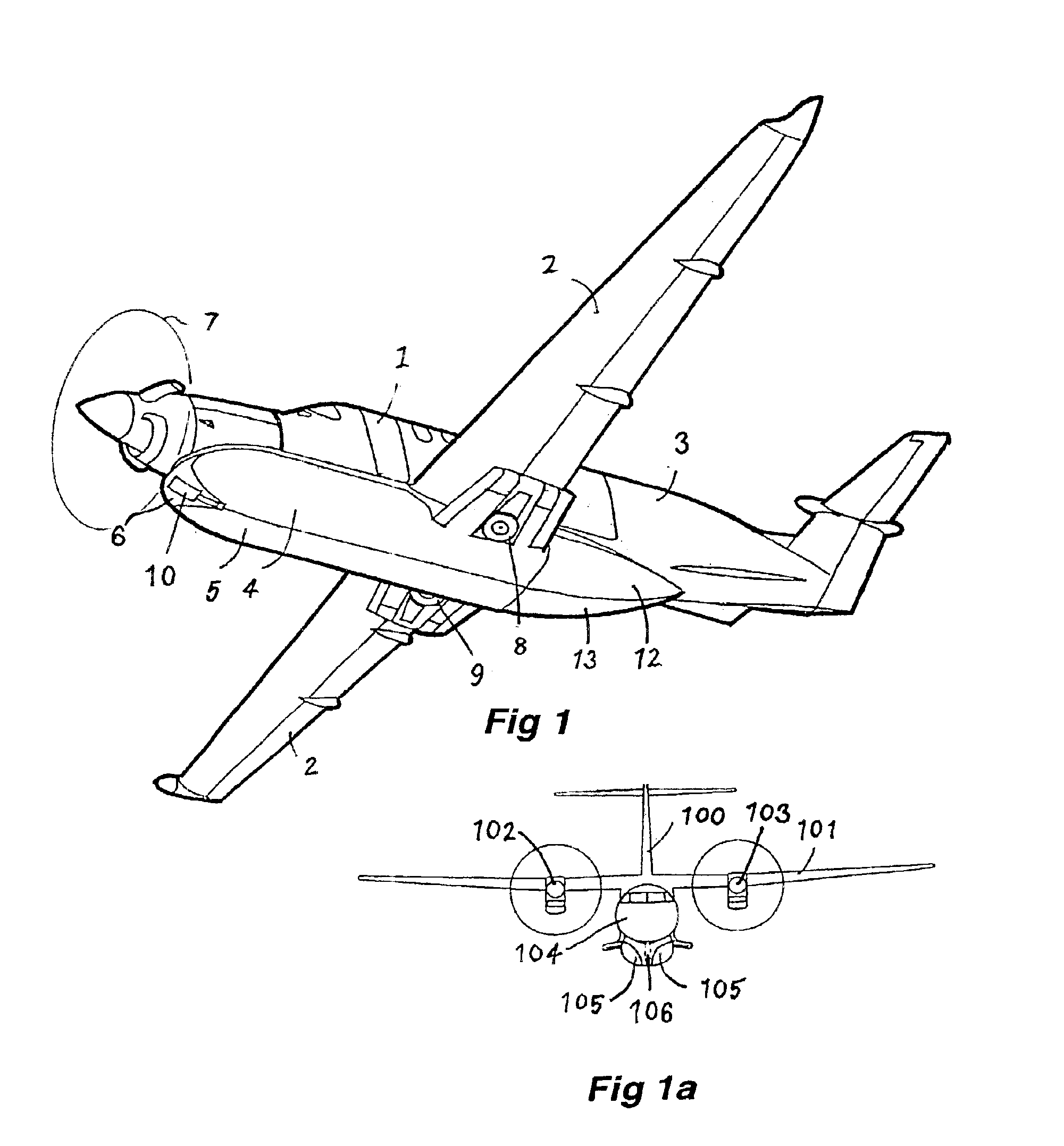
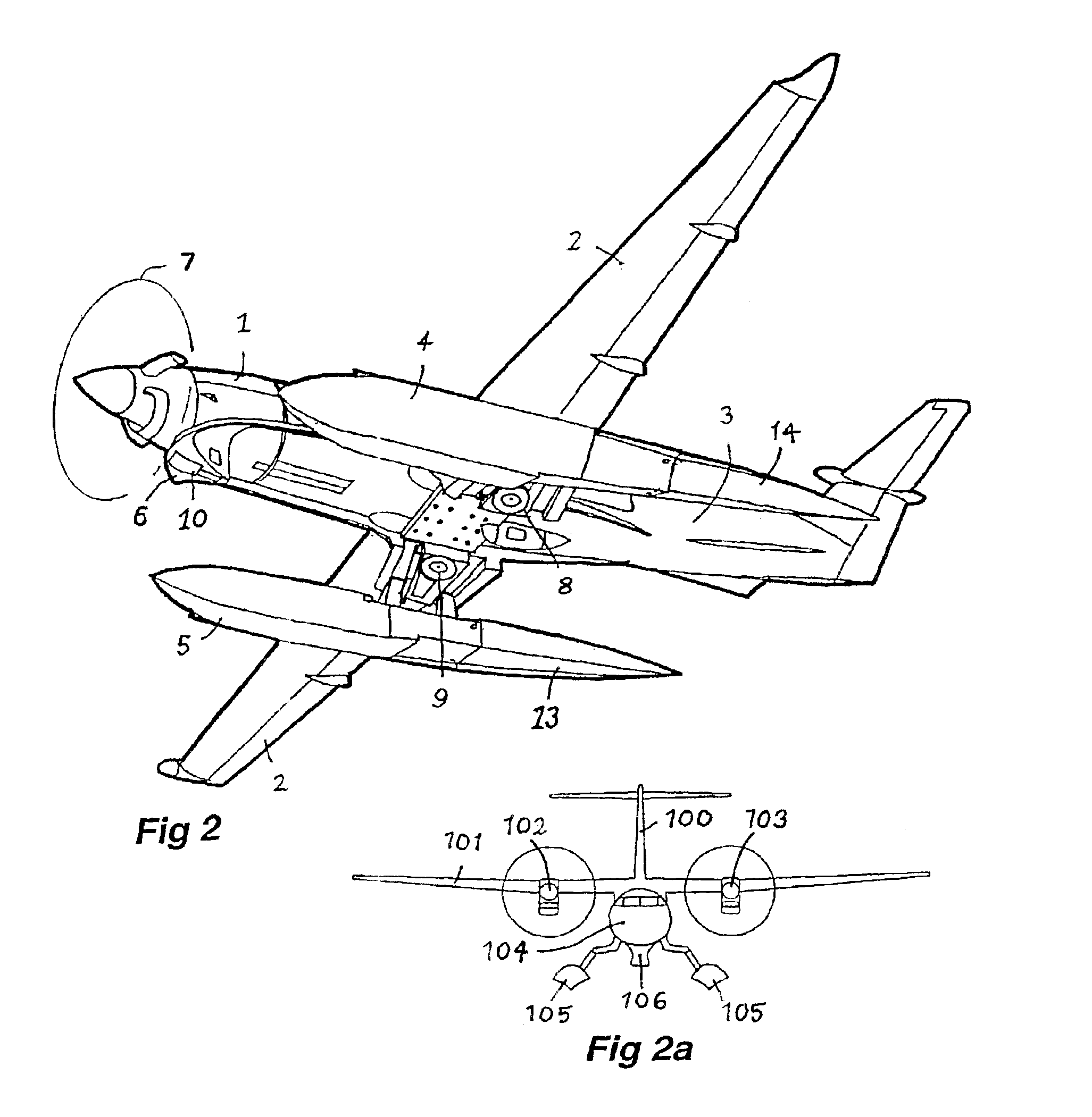
Now referring to the drawings and in particular to FIGS. 1, 2, 3, 4 and 5, each of these illustrate a twin float aircraft 1 which has fixed wings 2, a main body or fuselage 3, and extending through a forward to rearward alignment of the aircraft 1, floats 4 and 5.

The floats 4 and 5 in each case are positioned so as to be located in a retracted position at least, behind a fairing 6 which is secured beneath the fuselage 3 and positioned just behind the propeller 7. This fairing 6 forms thereby a portion of the main fuselage 3 which is at a forward part of the fuselage 3 and such that, in the retracted position, each of the floats 4 and 5 is positioned relative to the fairing 6 so that there is an alignment providing a substantially streamline shape across the fairing 6 and from the fairing 6 to each respective float 4 and 5 each of which is located behind the fairing 6.

In addition, in each case, there is shown appropriately, two side wheels 8 and 9 and a nose wheel 10.

There are simple...


PUM


Abstract

A twin float aircraft (1) which has a retractable float (4 and 5) for each side of a fuselage (3) providing buoyancy for the aircraft during take off and landing and reduced air resistance during flight with each of the floats (4 and 5) being articulated (12 and 13) to assist streamline alignment when retracted.

Description

This invention relates to twin float aircraft.TECHNICAL FIELDThe term “twin float aircraft” is used to distinguish aircraft having a float located to each side of a centre line aligned in a forward to aft alignment of the aircraft where the respective floats provide a substantial proportion at least of flotation for the aircraft and do not act merely as stabilisers.This then is to distinguish such aircraft from seaplanes which may have stabiliser floats depending from a respective wing.BACKGROUND ARTTwin float aircraft are well known and conventionally provide for a float to be fixedly secured to be positioned somewhat below and somewhat to a side in each case of a wing and a fuselage respectively.A main current issue is that having floats in this position are simply not aerodynamically efficient.One of the issues addressed by this invention is to provide an arrangement which allows for improvement of aerodynamic efficiency in connection with twin float aircraft.DISCLOSURE OF THE IN...

Claims


Application Information

Patent Timeline
IPC IPC(8): B64C25/00B64C25/16B64C25/12B64C25/54B64C25/66B64C35/00
CPCB64C25/12B64C25/16B64C35/008B64C25/66B64C25/54
Inventor SMITH, ALAN JOHNRUDDUCK, GRENFELL SAXON
Owner TIGERFISH AVIATION PTY LTD
Why Eureka
Try Eureka