
Latch mechanism for a vehicle

a technology for latching mechanisms and vehicles, applied in the field of latching, can solve the problems of loss of some resilience, insufficient sealing load, and insufficient sealing load, and achieve the effect of reducing the weight of the closure for the available sealing load

Inactive Publication Date: 2005-03-15
MERITOR TECH
View PDF10 Cites 20 Cited by
  • Summary
  • Abstract
  • Description
  • Claims
  • Application Information

AI Technical Summary

Benefits of technology

Accordingly, one aspect of the present invention provides a latch including a latch bolt movable between a primary latch position and an open position, a pawl moveable between a first engaged position where it secures the latch bolt in at least its primary latch position and a second released position where it releases the latch bolt from at least its first primary latch position, release means moveable between a rest position where it allows the pawl to achieve its first engaged position and an actuated position where it retains the pawl in its second released position, the latch bolt further including a secondary latch position, wherein the latch further comprises a capture means arranged so as to prevent engagement of the pawl in the secondary latch position during closure of the door, until the claw has rotated to a predetermined position beyond that at which engagement in the secondary latch position may otherwise occur.

Problems solved by technology

However, a number of circumstances exist in which the seal load is insufficient to achieve this.
For example, the seals surrounding the closure may have lost some of their resilience due to extended use, the weight of the closure may be too high for the available seal load, or there may be additional weight on the lift gate due to snow or ice that prevents the closure from being lifted beyond the secondary latch position.
Problems may also occur when the user releases the latch from inside the vehicle.
In this situation the closure initially clears the secondary latch position, but once the user exits the vehicle and slams the door, a build up of air pressure inside the vehicle lifts the closure which subsequently drops under the influence of its self weight and a vacuum induced inside the vehicle by the passenger door closing, thereby causing the latch to engage in the secondary latch position.
All of these occurrences are undesirable since they may put vehicle users to significant inconvenience due to a second attempt to release the closure being required.

Method used


Image

  • Latch mechanism for a vehicle
  • Latch mechanism for a vehicle
  • Latch mechanism for a vehicle

Examples


Embodiment Construction

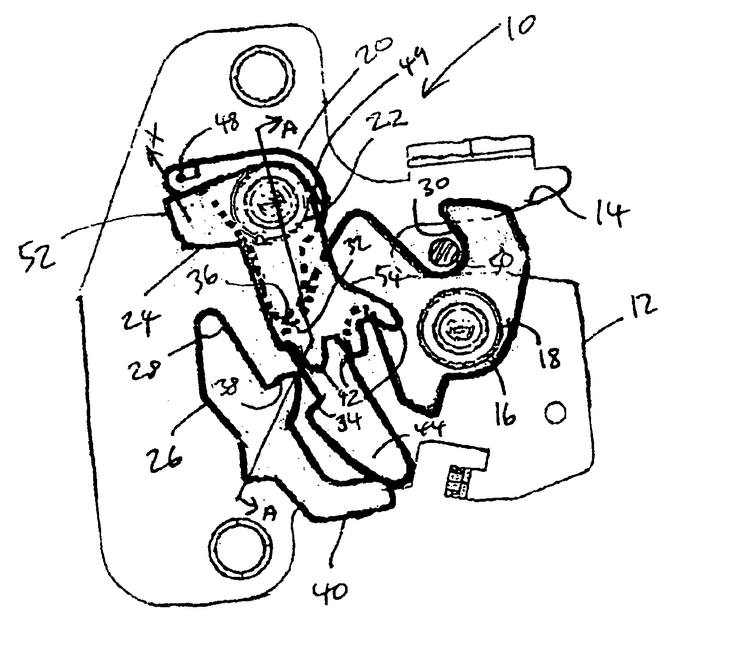
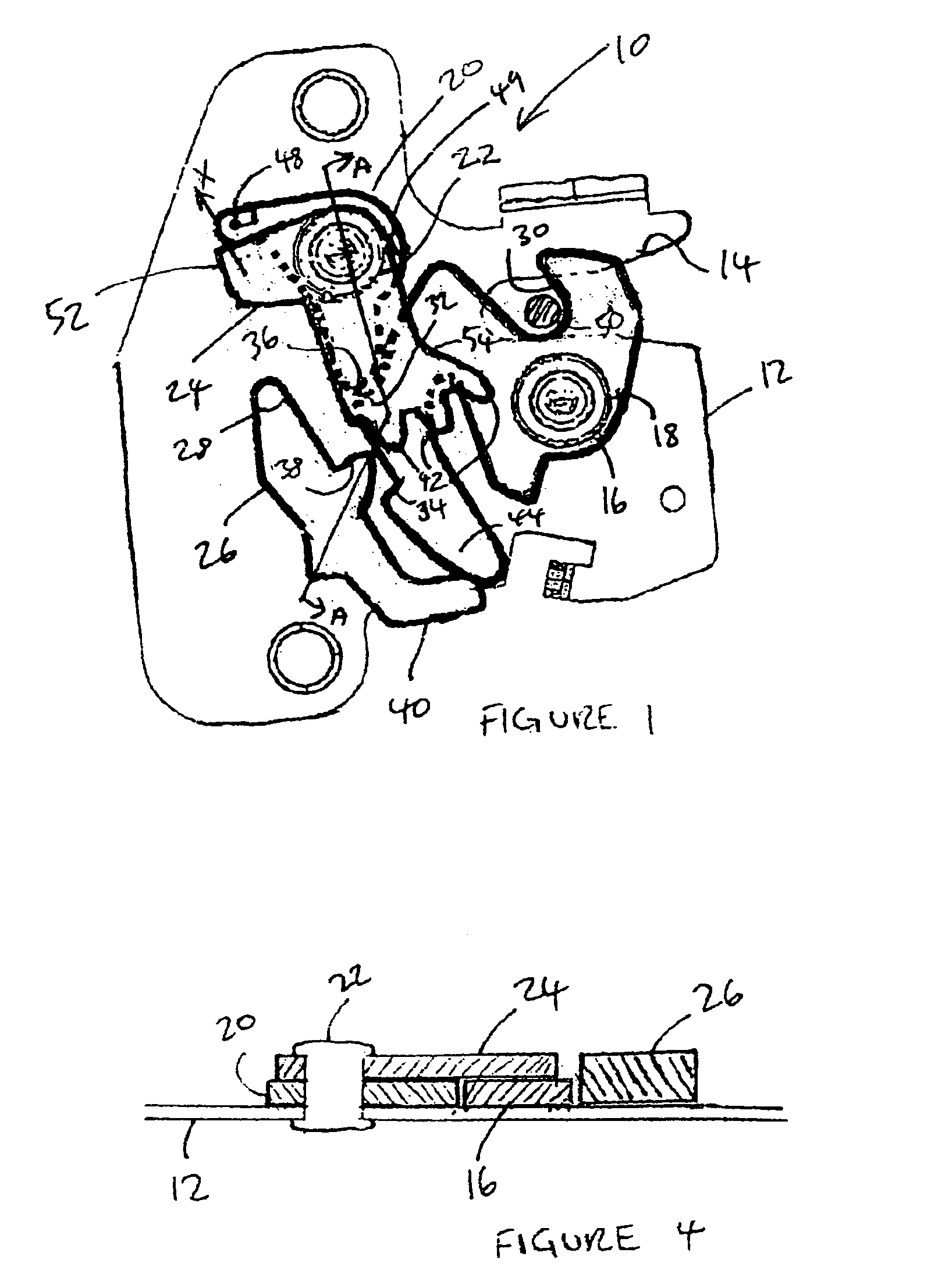
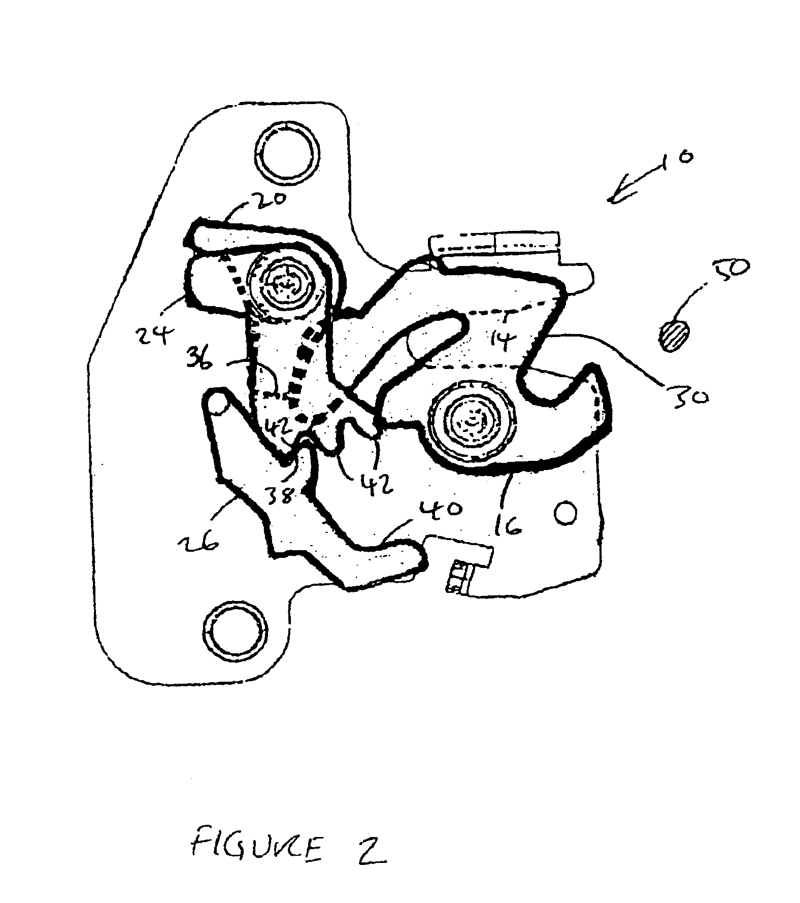
Referring to FIGS. 1 and 4, a latch 10 includes a chassis 12. The chassis 12 is provided with a mouth portion 14 and a latch bolt in the form of a claw 16 rotatable about a pivot pin 18 and resiliently biased into an open position. The claw 16 is arranged such that a mouth 30 thereof cooperates with the mouth portion 14 of the chassis 12 to releasably retain a striker 50. The latch 10 is further provided with a first abutment surface 32, a second abutment surface 34 and a projection 44, whose purpose is discussed in greater detail below.

A pawl 20 is rotatably mounted to the chassis 12 by a second pivot pin 22 and is resiliently biased into contact with the claw 16 by a helical spring (not shown) or other suitable means. The pawl 20 is provided with a pawl tooth 36 arranged to engage either the first abutment surface 32 or the second abutment surface 34. When the claw 16 is in a primary latch position, the first abutment surface 32 contacts the pawl 20. When the claw 16 is in a secon...


PUM


Abstract

A latch including a latch bolt movable between a primary latch position and an open position, a pawl moveable between a first engaged position where it secures the latch bolt in at least its primary latch position and a second released position where it releases the latch bolt from at least its first primary latch position, release means moveable between a rest position where it allows the pawl to achieve its first engaged position and an actuated position where it retains the pawl in its second released position, the latch bolt further including a secondary latch position, wherein the latch further comprises a capture means arranged so as to prevent engagement of the pawl in the secondary latch position during closure of the door, until the claw has rotated to a predetermined position beyond that at which engagement in the secondary latch position may otherwise occur.

Description

This application claims priority to Great Britain patent application number GB 0130858.4 filed on Dec. 22, 2001.BACKGROUND OF THE INVENTIONThe present invention relates to a latch. More particularly, but not exclusively the present invention relates to a latch for use with a lift gate (e.g. a hatchback or boot / trunk) of a vehicle.All vehicle closures that allow access to the passenger compartment of a vehicle must, according to current legislation, be provided with a secondary latch position to ensure that the door does not unintentionally open whilst the vehicle is in motion, even if the closure has not been closed to the primary latch position.As people carriers (minivans), off-road and estate (station wagon) vehicles have become increasingly prevalent on the car market, it has become necessary to fit latches having a secondary latch position to the rear tailgate / liftgate closures since seats are often provided in the rear part of the vehicle normally intended for luggage. In many...

Claims


Application Information

Patent Timeline
IPC IPC(8): E05B65/12E05B65/19E05B65/20
CPCE05B83/16E05B77/18E05B81/15Y10S292/43Y10S292/23Y10T292/1047Y10T292/1048Y10T292/1082
Inventor SPURR, NIGELLI, MARK HAOEVANS, MICHAEL
Owner MERITOR TECH
Learn More