Method and apparatus for removing and replacing bulb of push-button type electrical switch

a technology of push-button type and tool, which is applied in the direction of electrical equipment, contact mechanisms, legends, etc., can solve the problems of limited distance by which the tool may be placed over the bulb, and achieve the effect of reducing the opening siz

Inactive Publication Date: 2005-03-22
COLE JOSEPH W +1
View PDF26 Cites 13 Cited by
  • Summary
  • Abstract
  • Description
  • Claims
  • Application Information

AI Technical Summary

Benefits of technology

The present invention is lamp or bulb removal tool for use in removing and replacing a lamp of a push-button switch. The tool has a first end which defines a bulb-accepting opening. A plurality of tines surround at least a portion of the opening. The tines are movable. In a first position, the tines are preferably biased outwardly and the opening is sufficiently large to accept a bulb therein. In a second position, the tines are pressed inwardly, reducing the size of the opening and engaging a bulb therein.
To remove the bulb, the tines are pressed inwardly, such as by moving the slider downwardly along the body over the tines. As the tines move inwardly, they engage the bulb or compress the insert (when one exists) against the bulb. Upward movement of the tool then causes the bulb to be extracted from its socket. When the tines are released, the bulb may easily be removed from the tool.

Problems solved by technology

The distance by which the tool may be placed over the bulb may be limited by the stop.

Method used


Image

  • Method and apparatus for removing and replacing bulb of push-button type electrical switch
  • Method and apparatus for removing and replacing bulb of push-button type electrical switch
  • Method and apparatus for removing and replacing bulb of push-button type electrical switch

Examples


Embodiment Construction

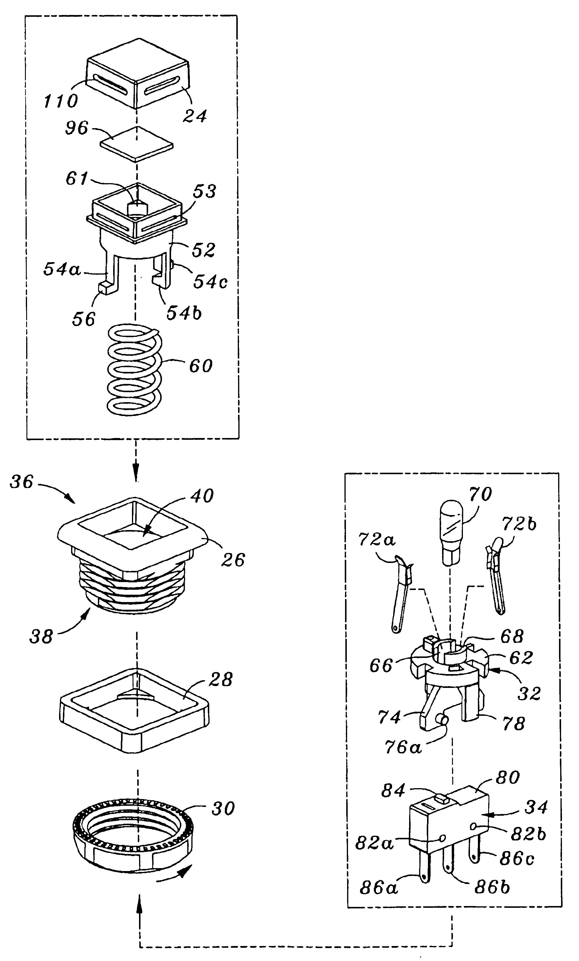
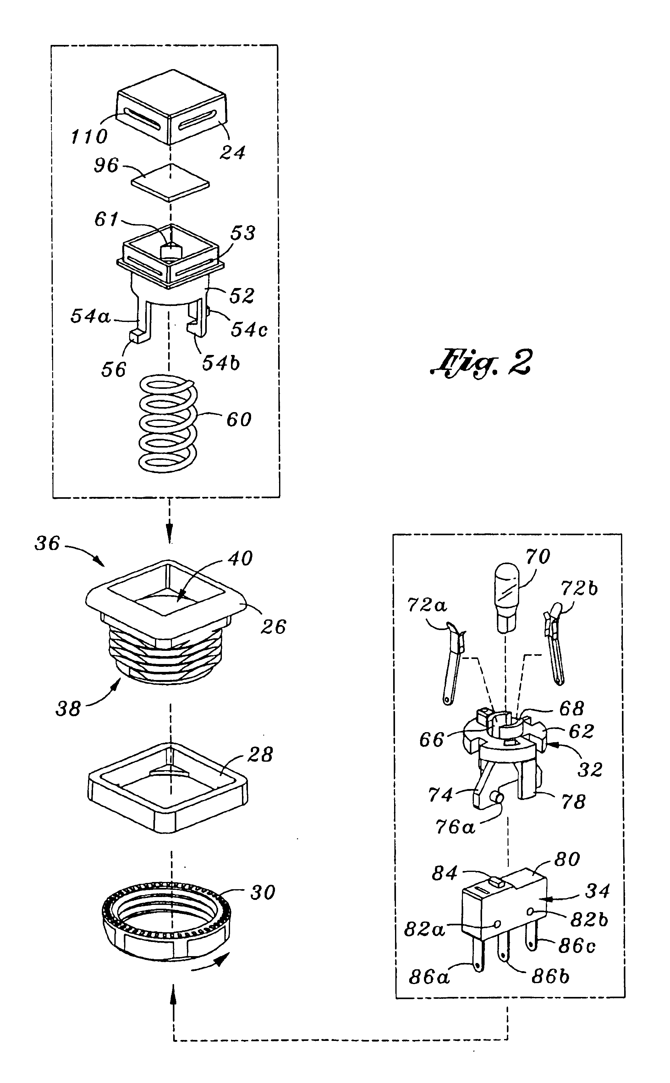
The invention is a method and apparatus for removing and replacing the bulb or lamp of a push-button type electrical switch. In the following description, numerous specific details are set forth in order to provide a more thorough description of the present invention. It will be apparent, however, to one skilled in the art, that the present invention may be practiced without these specific details. In other instances, well-known features have not been described in detail so as not to obscure the invention.

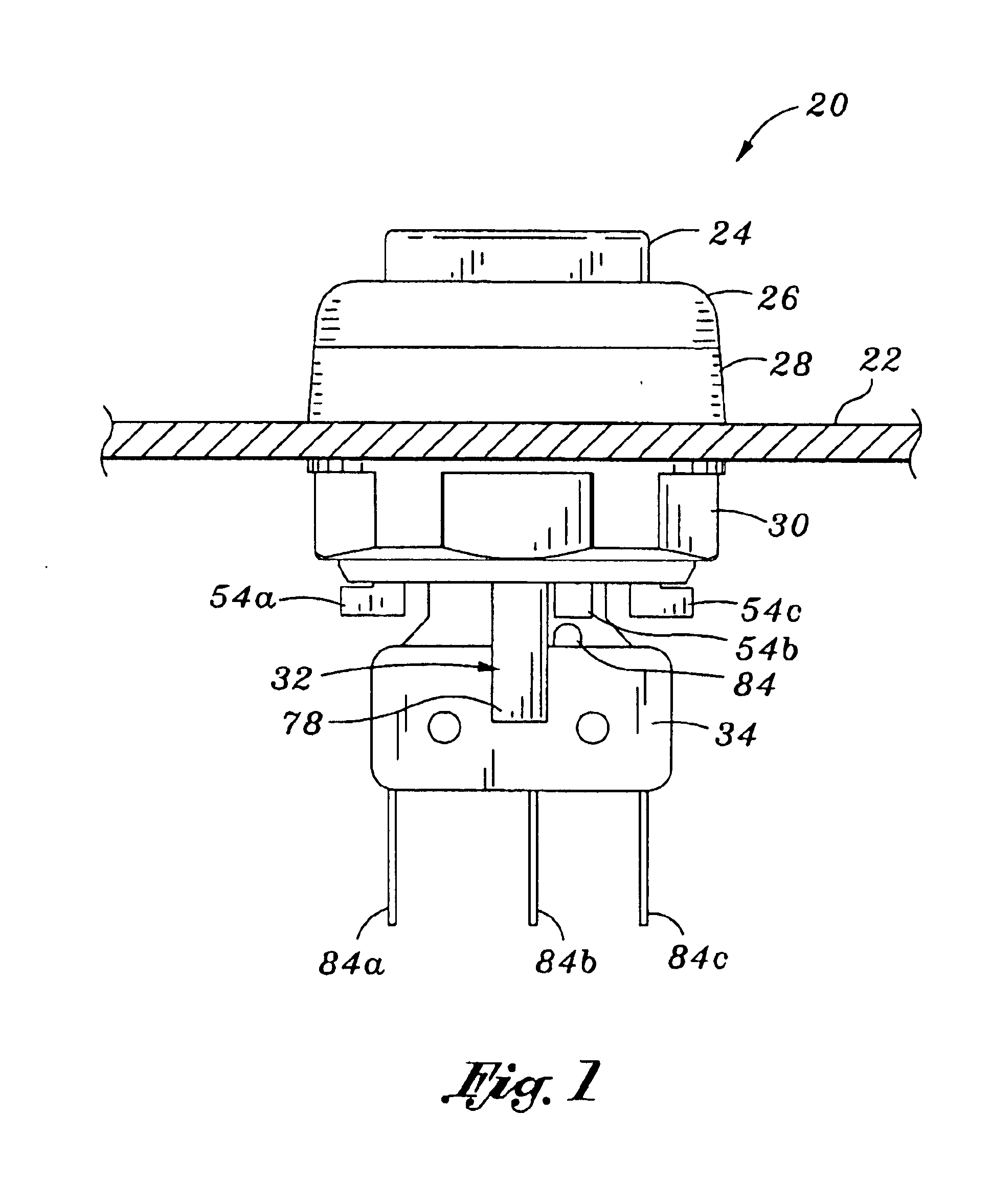
In general, the invention is tool which is useful in replacing the bulb of a push-button type electrical switch. Such a switch may have a variety of configurations. In one embodiment, the switch includes a push-button for actuating an electrical switch. The push-button electrical switch has a bulb or lamp for illuminating a portion of a body or housing of the push-button electrical switch.

A push-button electrical switch 20 of the type the tool of the invention is useful with will f...


PUM


Abstract

A tool for use in removing and replacing a bulb of a push-button type actuatable switch comprises a tool body having a first end defining a bulb-accepting opening. A plurality of tines surround at least a portion of the opening. When the tines are in a first position, the opening is sufficiently large to accept a bulb. When pressed inwardly, the tines reduce the size of the opening and engage a bulb located therein. Movement of a sleeve over the outside of the body presses the tines inwardly. In one embodiment, a flexible sleeve is located in the opening for gripping and protecting a bulb. A stop extends into the insert, limiting the extent to which a bulb may be pressed into the tool. An opposing end of the tool may include a prong or blade for engaging and removing a lens cover over a bulb.

Description

FIELD OF THE INVENTIONThe present invention relates to a tool for use in replacing the bulb of a push-button type electrical switch.BACKGROUND OF THE INVENTIONPush-button type switches are utilized in thousands of applications. One common application for push-button switches is as an input device for a gaming machine. For example, a gaming machine may include a plurality of push-buttons permitting a user to indicate a input, such as to “hold” a card, place a “bet” of a monetary amount, “deal” cards or the like.In many instances, gaming machines are located in areas of reduced illumination. The reduced illumination makes it easier for a player of the game to view information presented on a video display of the gaming machine. On the other hand, the reduced illumination makes it difficult for a player to observe other aspects of the gaming machine, such as the location of push-buttons. As a result, these gaming machine generally include a lamp for illuminating a push-button thereof.A ...

Claims


Application Information

Patent Timeline
Patent Type & Authority Patents(United States)
IPC IPC(8): H01H13/02H01H9/12H01H9/00H01H9/16
CPCH01H9/12H01H9/162H01H13/023H01H2229/042H01H2219/04H01H2219/042
Inventor COLE, JOSEPH W.MOU, OLIVER C.
Owner COLE JOSEPH W
Why Eureka
Try Eureka