Thermostatic valve control structure

a control structure and thermostatic valve technology, applied in the direction of functional valve types, process and machine control, instruments, etc., can solve the problems of affecting the axial movement, and achieve the effect of increasing the friction affecting the life of the rubber ring

Inactive Publication Date: 2011-06-23
DELUXE BRASSWARE
View PDF5 Cites 8 Cited by
  • Summary
  • Abstract
  • Description
  • Claims
  • Application Information

AI Technical Summary

Benefits of technology

[0004]Therefore, the primary object of the present invention is to solve the problem occurred to the conventional temperature sensor installed in a copper bushing and results in accumulation of water dregs that increases friction with the rubber ring and affects life span of the rubber ring.

Problems solved by technology

Excessive friction also hinders the axial movement of the temperature sensor 1 and causes clogging.

Method used


Image

  • Thermostatic valve control structure
  • Thermostatic valve control structure
  • Thermostatic valve control structure

Examples


Embodiment Construction

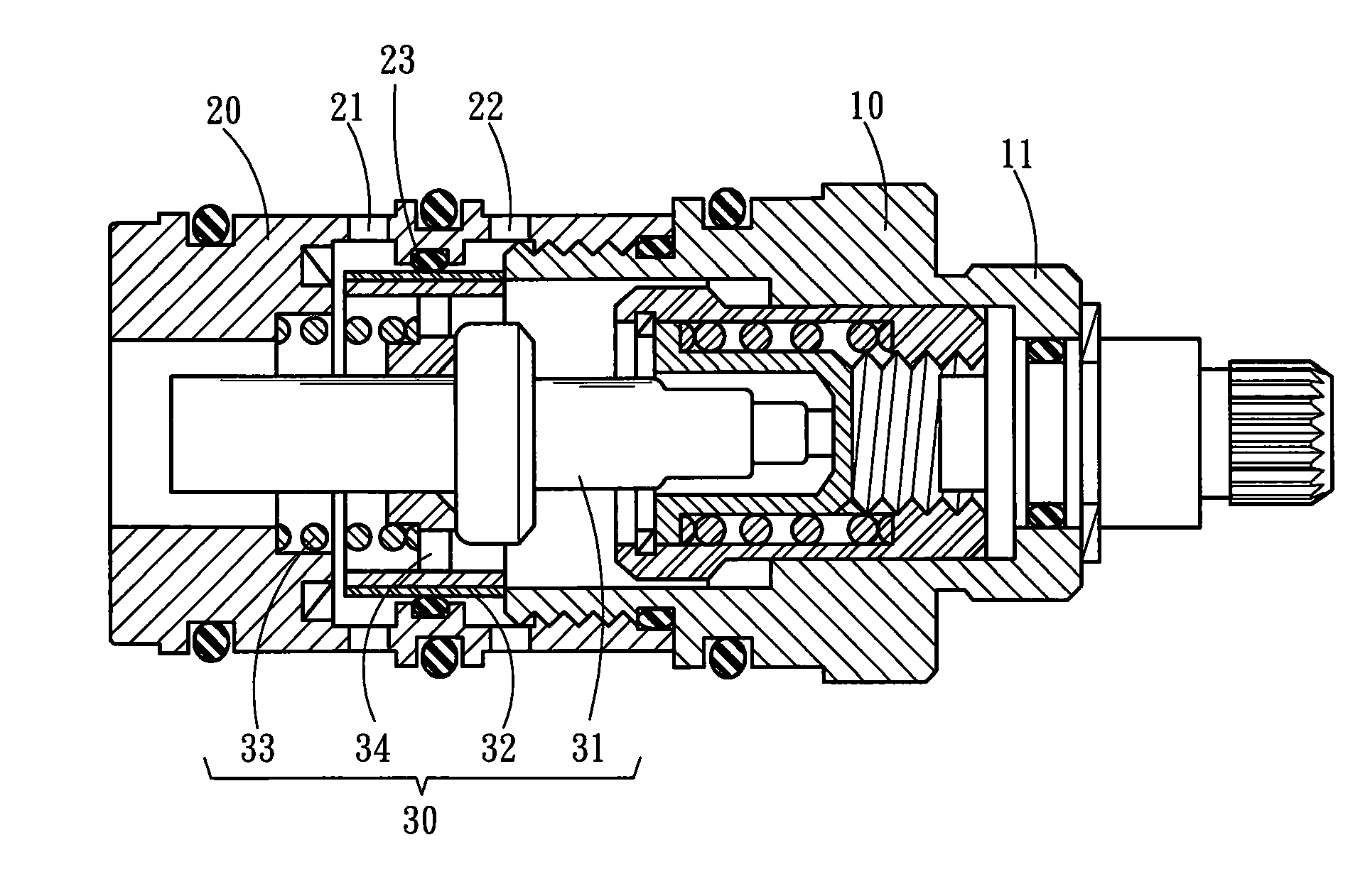
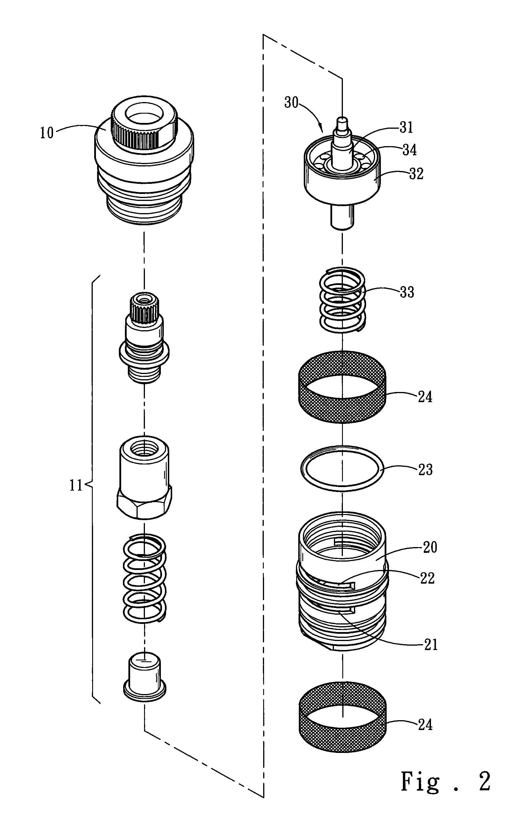
[0014]Please refer to FIGS. 2 and 3, the present invention provides a thermostatic valve control structure which comprises a rotary element 10, a water intake case 20 coupling with the rotary element 10 and an axial movement element 30 located in the water intake case 20. The rotary element 10 has an axis with a regulating portion 11 located therein that is axially extensible by turning. The water intake case 20 is coupled with the rotary element 10 by screwing, and has a hot water inlet 21, a cold water inlet 22 and a sealing ring 23. The sealing ring 23 is interposed between the hot water inlet 21 and the cold water inlet 22. The axial movement element 30 has a temperature sensing bar 31 and a ceramic layer 32 covered on the surface thereof. The temperature sensing bar 31 has one end butting the regulating portion 11 and the other end coupling with an elastic element 33. The elastic element 33 is held in the water intake case 20. The axial movement element 30 is movable axially th...


PUM


Abstract

A thermostatic valve control structure mainly has an axial movement element movable axially to control opening size of a hot water inlet and a cold water inlet. The axial movement element has a ceramic layer which has a smooth surface to reduce friction with a sealing ring. The ceramic layer provides advantages of resisting acid and alkali, less likely to accumulate water dregs, simpler structure and longer life span. Thus the total life span and durability of the thermostatic valve control structure can be enhanced.

Description

FIELD OF THE INVENTION[0001]The present invention relates to a temperature control structure and particularly to a thermostatic valve control structure equipped with a ceramic layer.BACKGROUND OF THE INVENTION[0002]Applicant submitted a temperature sensor apparatus disclosed in R.O.C. patent pub. No. 347039 to provide constant temperature for a faucet as shown in FIG. 1. It includes a temperature sensor 1 to detect temperature, an axial bolting set 2 to assist the temperature sensor 1 to move axially and an annular compression spring 3 to provide a counterforce on the temperature sensor 1. By opening the faucet and setting water discharge temperature, a constant water temperature can be maintained through the temperature sensor 1.[0003]The temperature sensor 1 is installed in a copper bushing 4 and generates friction with a rubber ring 5 held in the temperature sensor 1 during axial movement thereof. The copper bushing 4 also tends to accumulate water dregs to increase additional fr...

Claims


Application Information

Patent Timeline
Patent Type & Authority Applications(United States)
IPC IPC(8): F16K17/38
CPCG05D23/1353F16K11/044Y10T137/7737Y10T137/86823
Inventor HONG, MINNAN
Owner DELUXE BRASSWARE
Why Eureka
Try Eureka