
Variable fan duct nozzle

a technology of fan duct nozzle and variable nozzle, which is applied in the direction of engine components, machines/engines, jet propulsion plants, etc., can solve the problems of adding even more undesired weight to the nacelle, complicated operation of the outer flow surface, and negatively affecting the performance of the nozzl

Active Publication Date: 2011-11-10
SPIRIT AEROSYSTEMS
View PDF24 Cites 8 Cited by
  • Summary
  • Abstract
  • Description
  • Claims
  • Application Information

AI Technical Summary

Benefits of technology

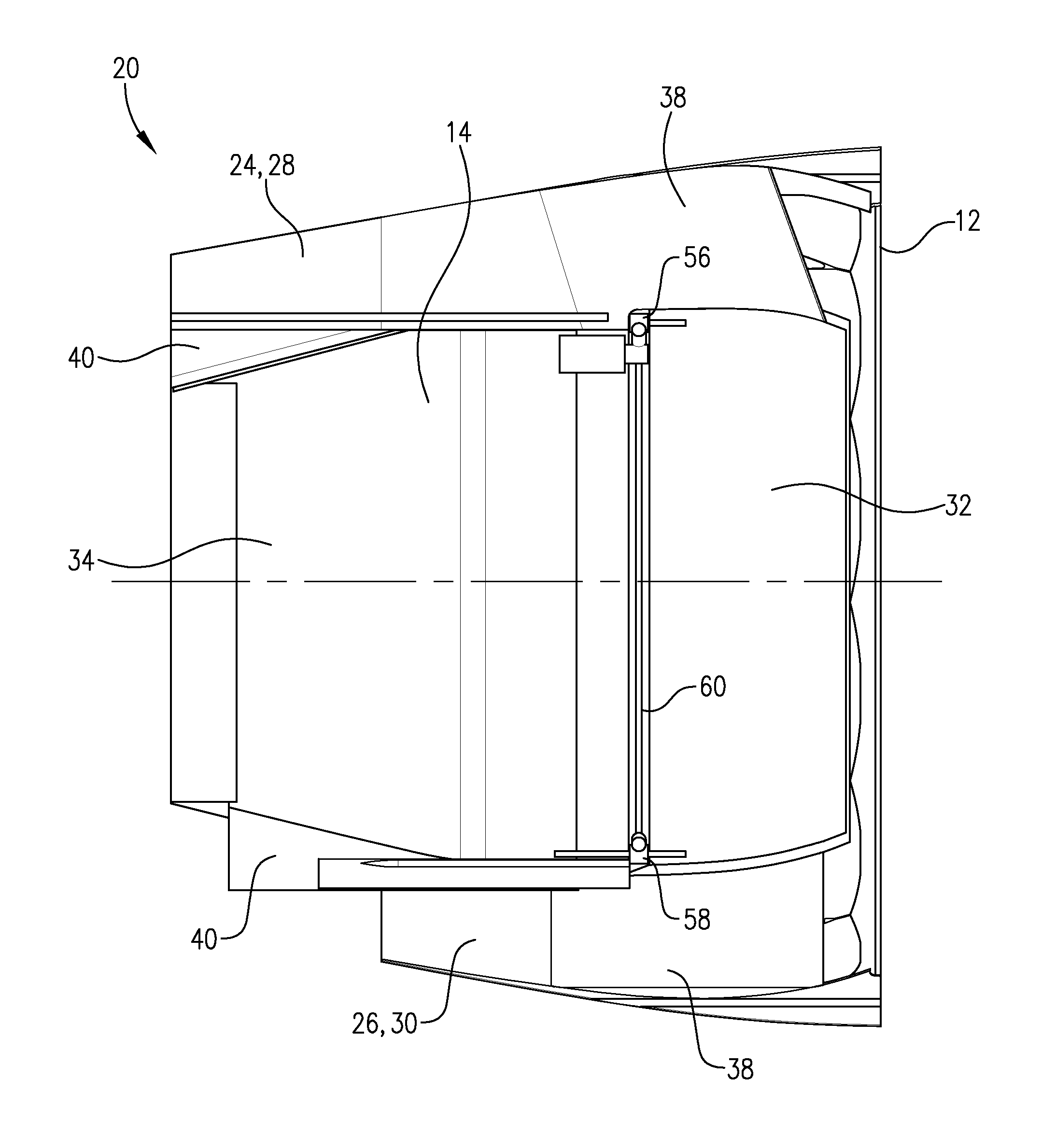
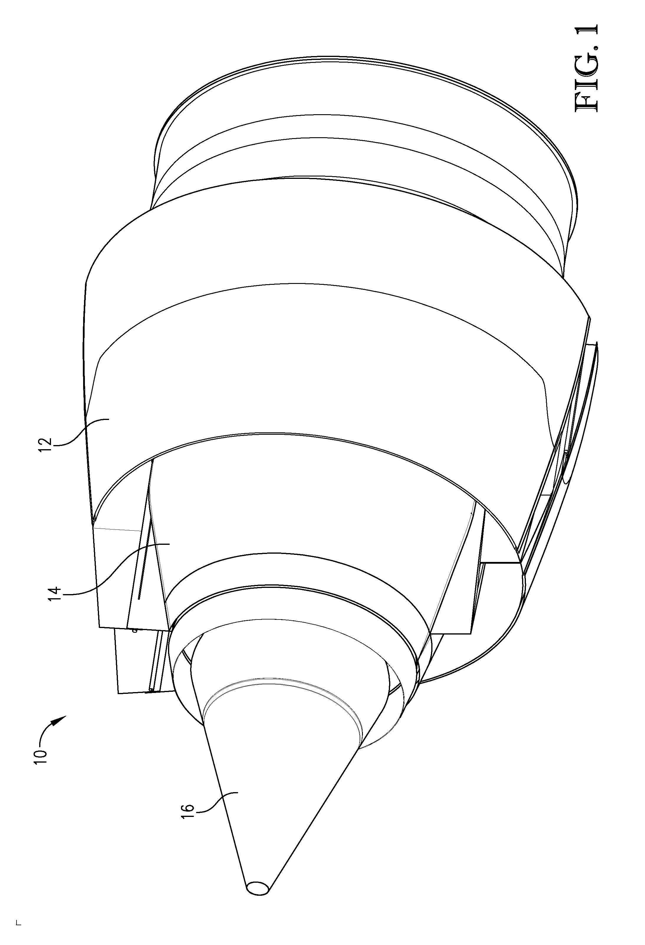
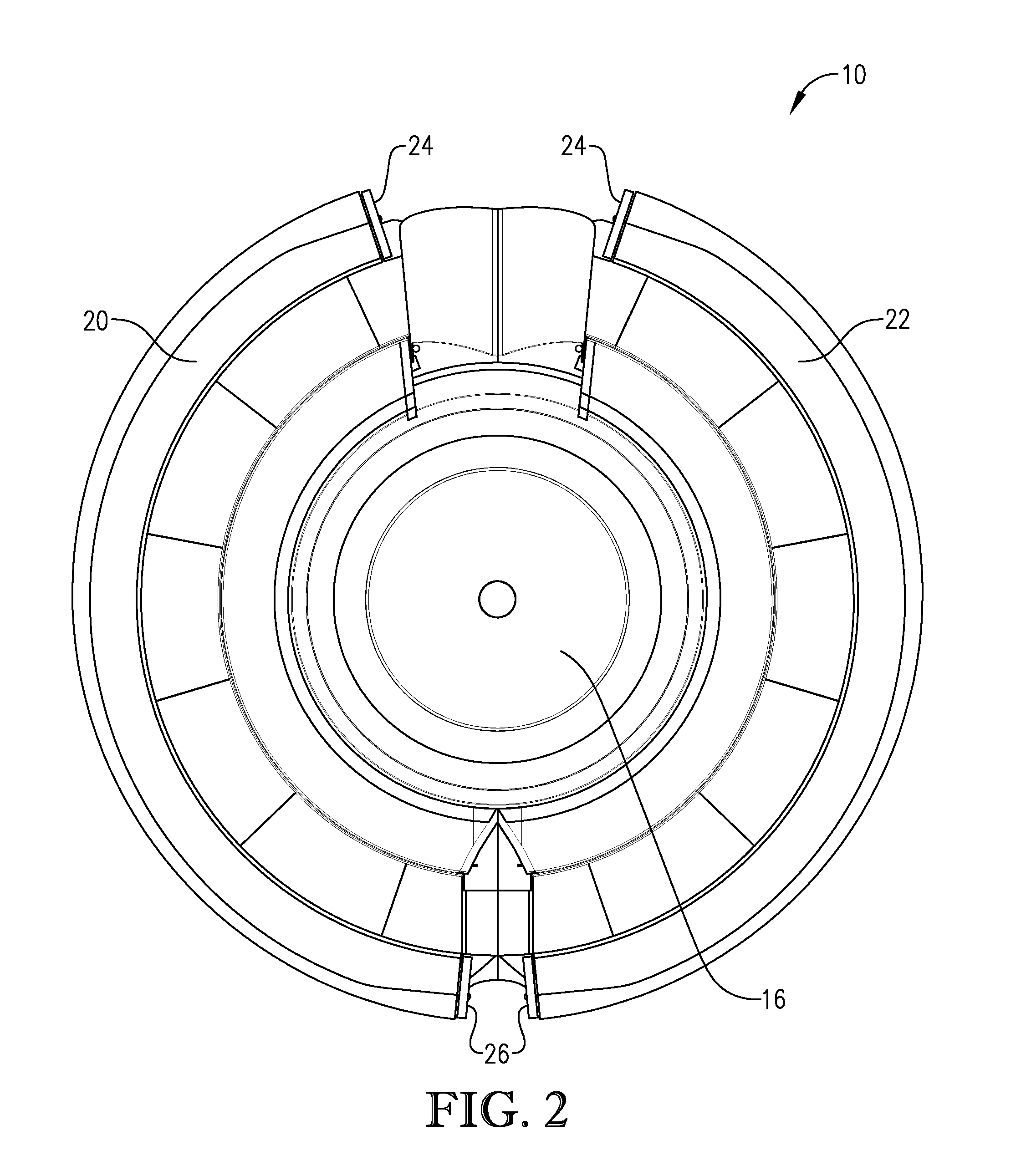
[0012]An aircraft nacelle constructed in accordance with an embodiment of the present invention comprises an outer cowl and an inner cowl located inward of the outer cowl with an air flow path formed therebetween. The nacelle may substantially surround an aircraft engine about an imaginary center axis. The inner cowl may comprise a forward portion and an aft portion slidable in a forward-to-aft direction via one or more actuators of the nacelle. When translated aftward, the aft portion may decrease the opening size of the fan duct's nozzle or exit opening.
[0014]In operation, the aft portion may be translated in a forward-to-aft direction away from the forward portion of the inner cowl from a first position to a second position. Moving the aft portion from the first position to the second position may decrease an aft exit area for the air flowing between the outer cowl and inner cowl.

Problems solved by technology

However, manipulating the outer flow surface can be complicated, particularly if the nacelle comprises a translating sleeve thrust reverser with its own actuators and moving parts.
However, this also increases the possibility of fan duct leakage at joints of the movable inner surface, negatively affecting the performance of the nozzle.
Moreover, these movable inner surfaces can be heavy and require robust activation or manipulation components, which add even more undesired weight to the nacelle.
Some manipulated inner flow surfaces reduce the fan duct's area more at a location forward of the fan duct's exit than at the fan duct's exit, decreasing air flow efficiency.
Furthermore, the location, size, and number of seams or joints of a variable nozzle can create undesired air leakage paths, causing premature wear on various components.

Method used


Image

  • Variable fan duct nozzle
  • Variable fan duct nozzle
  • Variable fan duct nozzle

Examples


Embodiment Construction

[0032]The following detailed description of the invention references the accompanying drawings that illustrate specific embodiments in which the invention can be practiced. The embodiments are intended to describe aspects of the invention in sufficient detail to enable those skilled in the art to practice the invention. Other embodiments can be utilized and changes can be made without departing from the scope of the present invention. The following detailed description is, therefore, not to be taken in a limiting sense. The scope of the present invention is defined only by the appended claims, along with the full scope of equivalents to which such claims are entitled.

[0033]In this description, references to “one embodiment”, “an embodiment”, or “embodiments” mean that the feature or features being referred to are included in at least one embodiment of the technology. Separate references to “one embodiment”, “an embodiment”, or “embodiments” in this description do not necessarily ref...


PUM


Abstract

An aircraft nacelle comprising an outer cowl and an inner cowl located inward of the outer cowl with an air flow path formed therebetween. The inner cowl may comprise a forward portion and an aft portion slidable in a forward-to-aft direction via one or more actuators. When translated aftward, the aft portion may decrease the area of the nacelle's fan duct nozzle. The greatest radial distance between the inner cowl and a center axis of the nacelle may occur at or forward of a location in which the forward and aft portions overlap each other. The forward portion may be comprised of a different material than the aft portion.

Description

BACKGROUND[0001]1. Field[0002]Embodiments of the present invention relate to aircraft nacelles and fan duct nozzles.[0003]2. Related Art[0004]An aircraft nacelle is a structure that surrounds an aircraft engine and broadly includes an inner cowl surrounding the engine and an outer cowl positioned outward of the inner cowl, forming an air duct or fan duct therebetween. Air flows in a forward to aft direction through the fan duct and out through an opening at an aft end of the nacelle, sometimes referred to as a nozzle.[0005]In some applications, it is desired to vary the area of the nozzle. For example, by increasing the area of the nozzle during aircraft take-off, a fan within the nacelle is allowed to operate at a lower fan pressure ratio (FPR). This can increase the aircraft's engine efficiency, leading to reduced noise. Lowering the FPR enhances the fan stability and reduces its potential to stall. The nozzle area can be decreased as air temperature and density decrease at higher...

Claims


Application Information

Patent Timeline
IPC IPC(8): F02K1/08
CPCF02K1/08F02K1/06F05B2280/5002
Inventor WEST, RANDALL RAY
Owner SPIRIT AEROSYSTEMS
Learn More