
Method and apparatus for eye-opening based optimization

Active Publication Date: 2008-07-15
SYNOPSYS INC
View PDF3 Cites 9 Cited by
  • Summary
  • Abstract
  • Description
  • Claims
  • Application Information

AI Technical Summary

Benefits of technology

[0012]Other types of search procedures can be used. For example, search procedures can be used that continue in a particular direction of parametric adjustment even if one or more steps of adjustment temporarily produce a decrease in eye opening size. Such search procedures can therefore avoid a localized minima.

Problems solved by technology

However, in “real world” situations, involving actual DTS equipment, noise disturbances can come from multiple types of sources, with each source having very different characteristics.
Thus, selecting a particular cost function, by which to optimize the parameters of a piece of DTS equipment, does not necessarily yield, on a consistent basis, the best improvement in a receiver's bit error rate.
However, this type of cost function cannot usually be expressed in a closed form that would make it tractable.

Method used


Image

  • Method and apparatus for eye-opening based optimization
  • Method and apparatus for eye-opening based optimization
  • Method and apparatus for eye-opening based optimization

Examples


Embodiment Construction

[0041]Reference will now be made in detail to preferred embodiments of the invention, examples of which are illustrated in the accompanying drawings. Wherever possible, the same reference numbers will be used throughout the drawings to refer to the same or like parts.

[0042]

Table of Contents to Detailed Description1.Overview2.Eye Opening Size3.Eye Opening Measurement 3.1. Eye Edge Location 3.2. Pseudocode For Eye Opening Measurement4.Hardware Implementation 4.1. Slicing and Measuring Unit 140 4.2. Example Optimizing Receiver5.Glossary of Selected Terms

1. Overview

[0043]The performance of a DTS receiver can be measured by the size of its “eye openings.” Eye opening size is defined in the below section 2: “Eye Opening Size.”

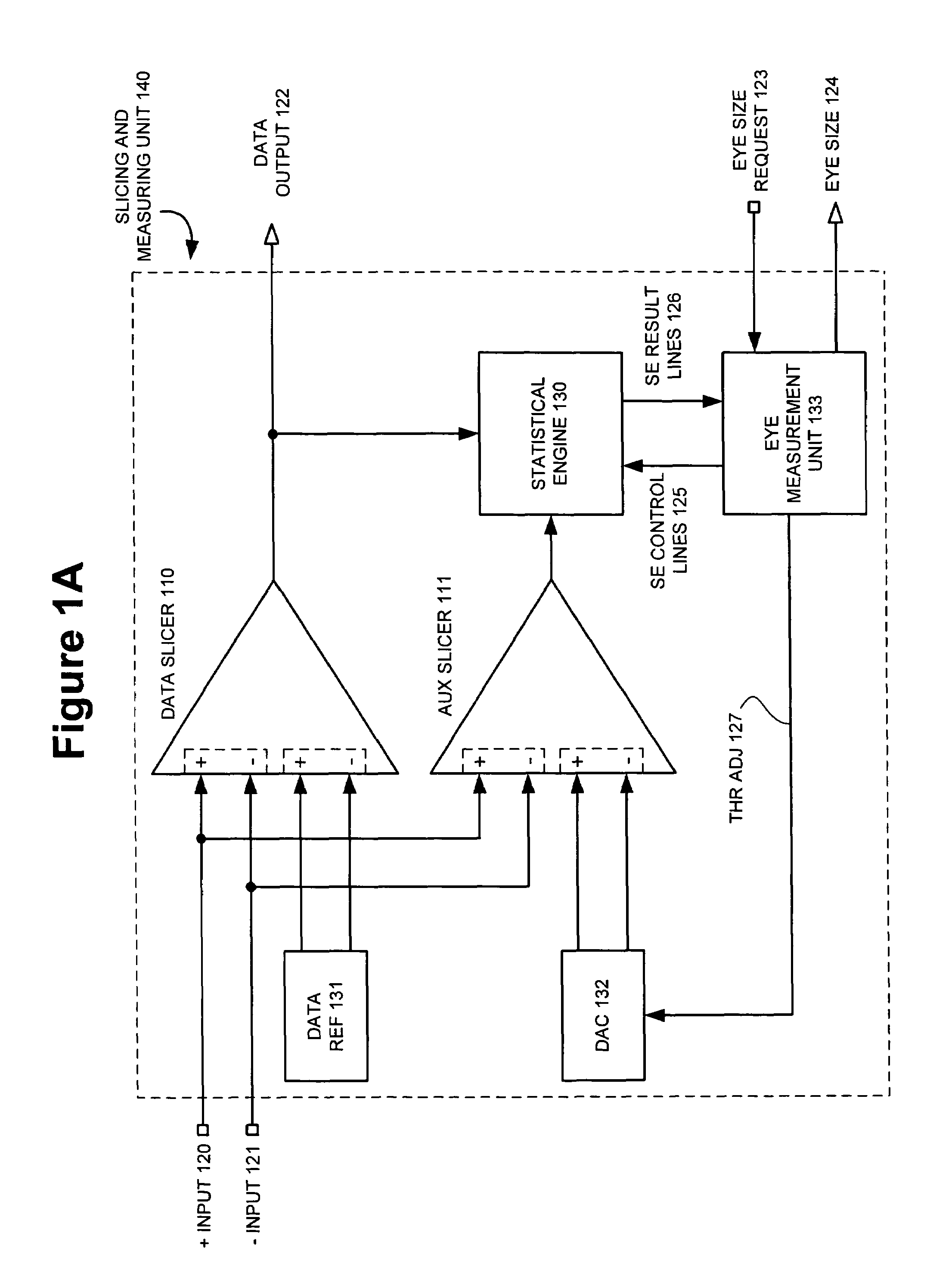
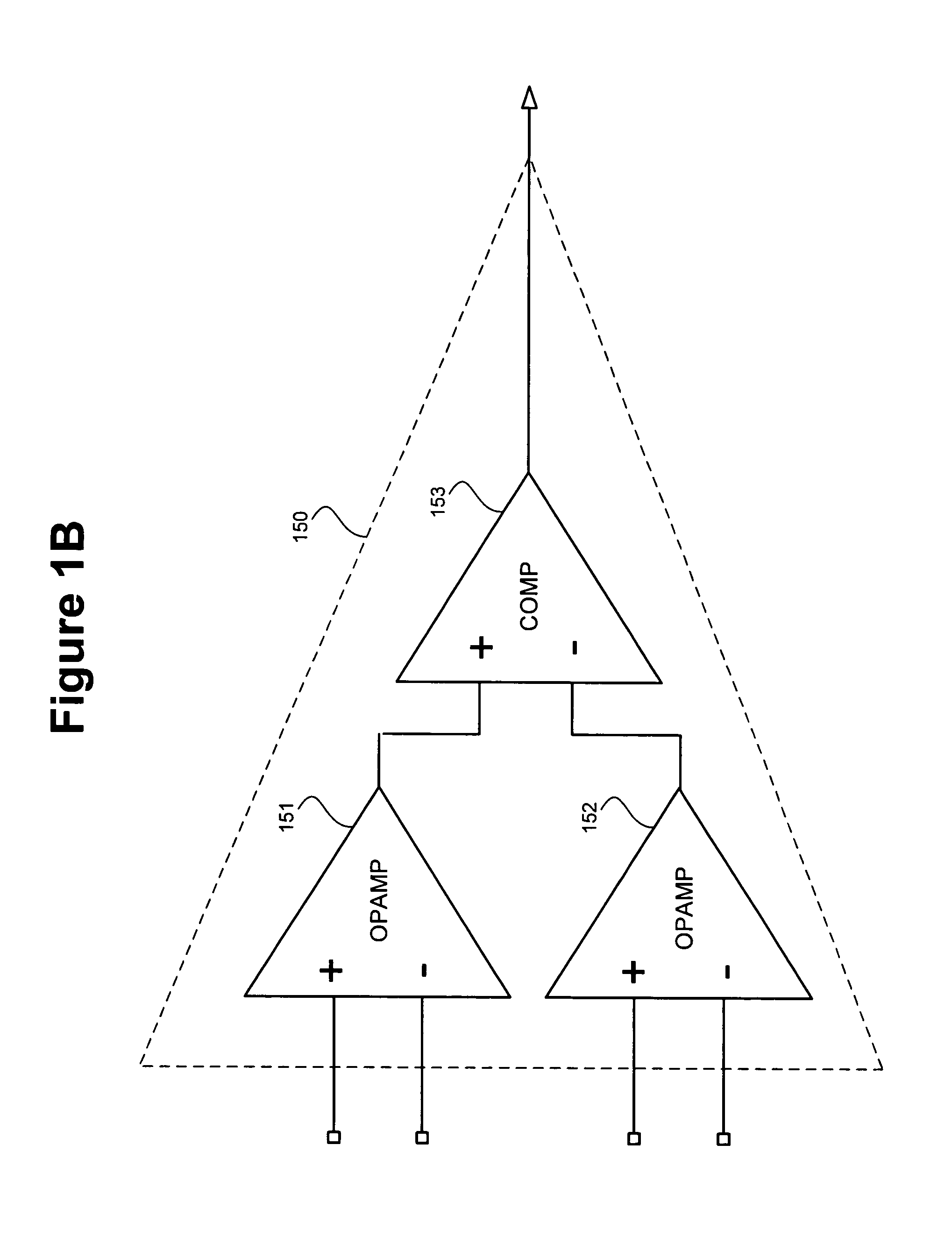
[0044]The measurement of eye opening size can be accomplished, without interrupting the normal operation of a receiver in a DTS, by utilizing two types of slicers: a data slicer and an auxiliary slicer. Measurement of eye opening size, using these two types of slicer...


PUM


Abstract

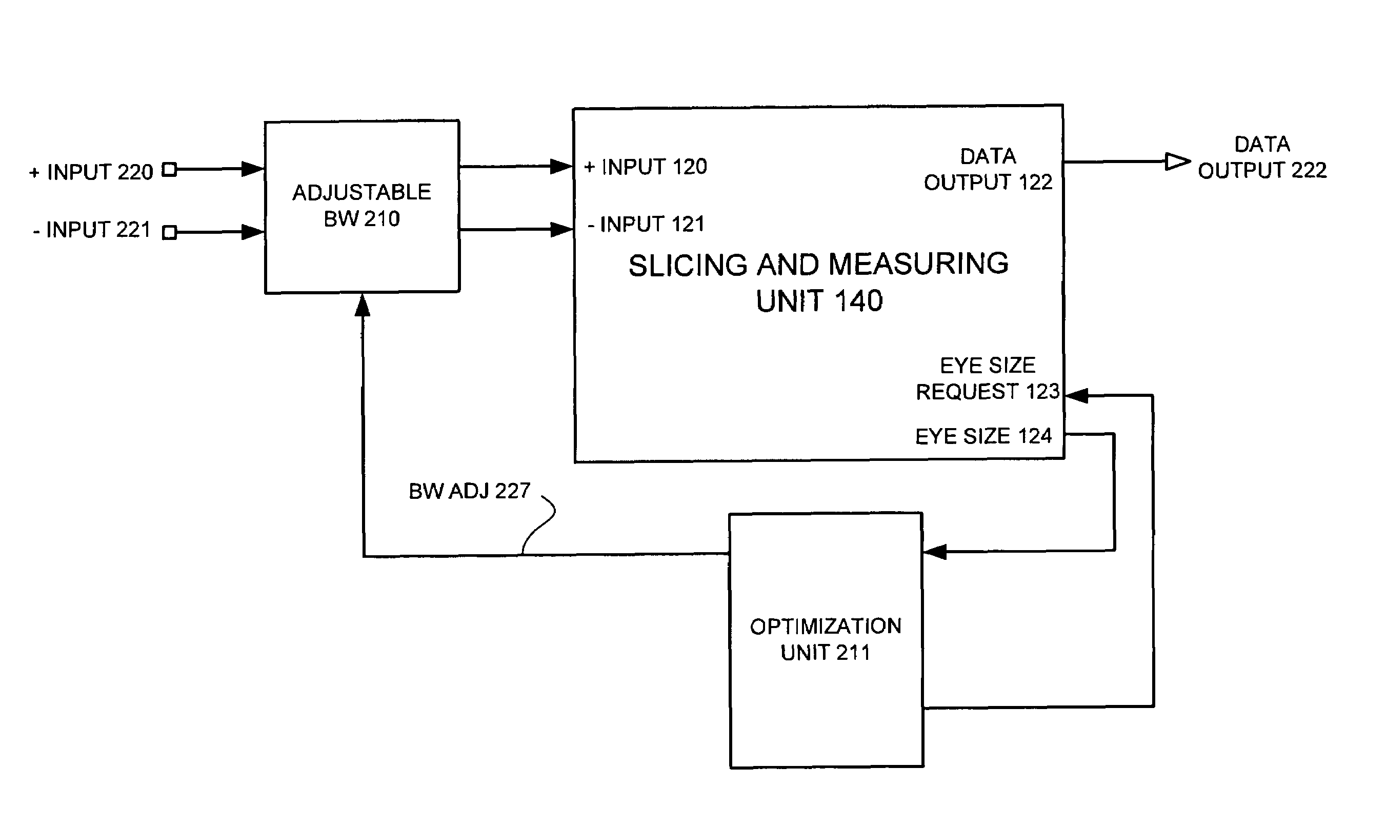
An eye opening measurement technique, that does not interrupt a receiver's normal operation, is used as a metric for optimizing any selected parameters of the receiver's operation. If eye opening size decreases, as a result of a change to a receiver parameter, the polarity for stepwise changes is reversed such that the next change is in the opposite direction. Other types of search procedures can be used.Eye opening size is the difference between the eye's upper and lower edges. Measurement of eye opening size is accomplished using a data and auxiliary slicer that find each “edge” of an eye opening based upon the slicers' level of agreement.Depending upon the level of agreement, and whether symbols of the upper or lower region of the eye are counted, the threshold of the auxiliary slicer can be adjusted in the direction necessary to converge on the eye edge sought.

Description

FIELD OF THE INVENTION[0001]The present invention relates generally to techniques for optimizing receivers in a data transmission system.BACKGROUND OF THE INVENTION[0002]In the operation of receivers, as part of a data transmission system (DTS), it can be desirable to incorporate optimization procedures that modify certain parameters of the receiver.[0003]One approach, is to adjust receiver parameters according to a cost function that measures some type of error. Example cost functions are minimum energy or min-max. Such cost functions can be shown to be effective with respect to a particular type of statistical noise model and a given set of environmental conditions. However, in “real world” situations, involving actual DTS equipment, noise disturbances can come from multiple types of sources, with each source having very different characteristics. Within a single piece of DTS equipment, that serves multiple data links, noise characteristics can vary widely across the links. Also, ...

Claims


Application Information

Patent Timeline
IPC IPC(8): H04B1/10
CPCH04L25/063
Inventor SONNTAG, JEFFREY LEESTONICK, JOHN THEODOREWEINLADER, DANIEL KEITH
Owner SYNOPSYS INC
Learn More