Lanyard and lanyard with an electrical cable

Inactive Publication Date: 2005-03-29
NEW YORK AIR BRAKE CORP
View PDF21 Cites 32 Cited by
  • Summary
  • Abstract
  • Description
  • Claims
  • Application Information

AI Technical Summary

Benefits of technology

The lanyard can be further comprised, if desired, as previously described herein, regarding the material of the strap and loops, the attachment of the loops to the strap and the structure of the first and second connectors. Also, the first length

Problems solved by technology

This results in additional wires and chains dangling from the end of each car and between the cars.
Attempts to restrain the hoses and cables between cars has resulted in a hodge-podge of field solutions that have failed to satisfactorily prevent cable and hose entanglements or damage or even outright breakage of the hoses, cables and connections.
The problem is compounded by the fact that the differing lengths of the electrical cables used to connect the electrical system between rail cars has resulted in sporadic an

Method used


Image

  • Lanyard and lanyard with an electrical cable
  • Lanyard and lanyard with an electrical cable
  • Lanyard and lanyard with an electrical cable

Examples


Embodiment Construction

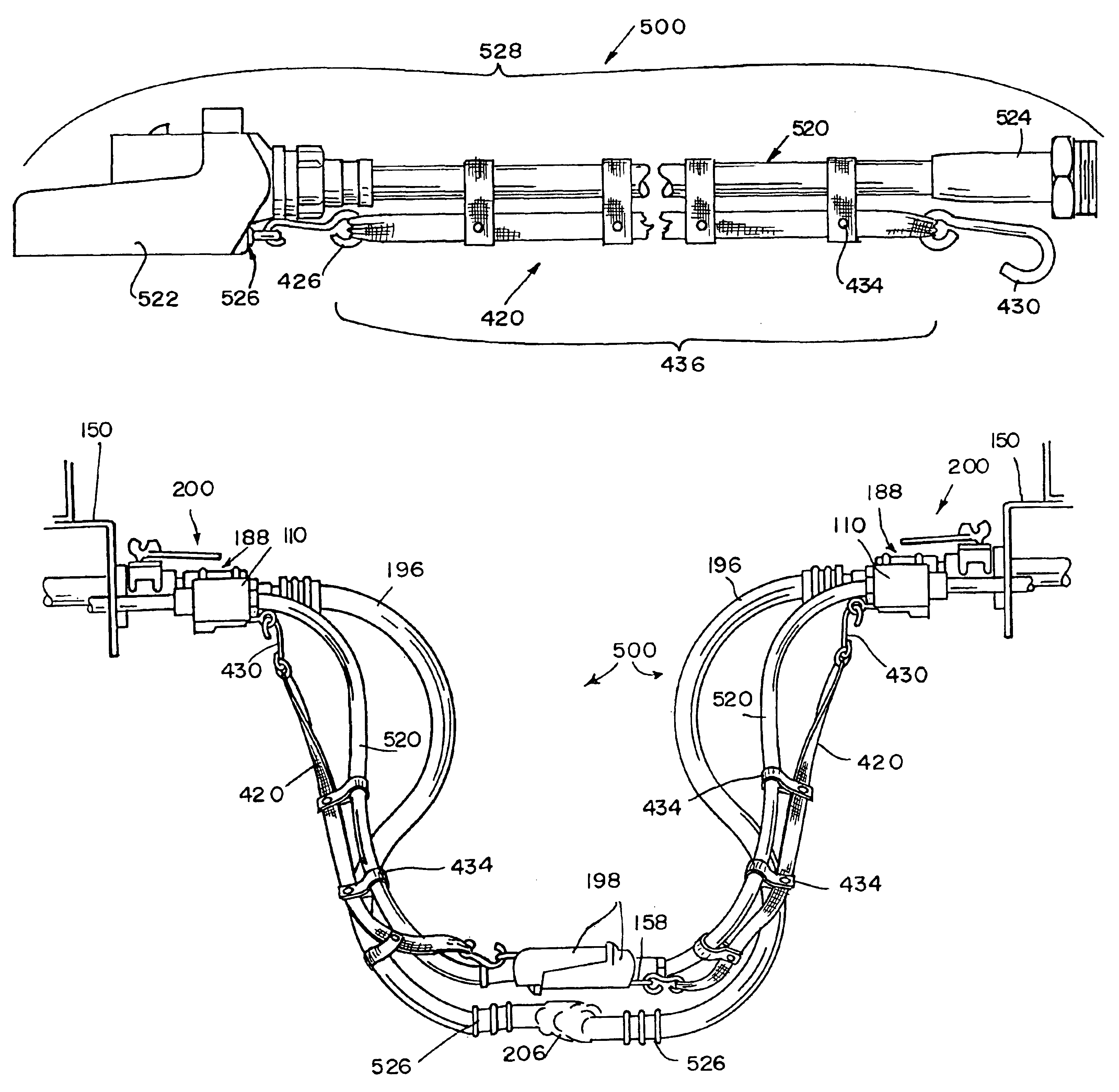
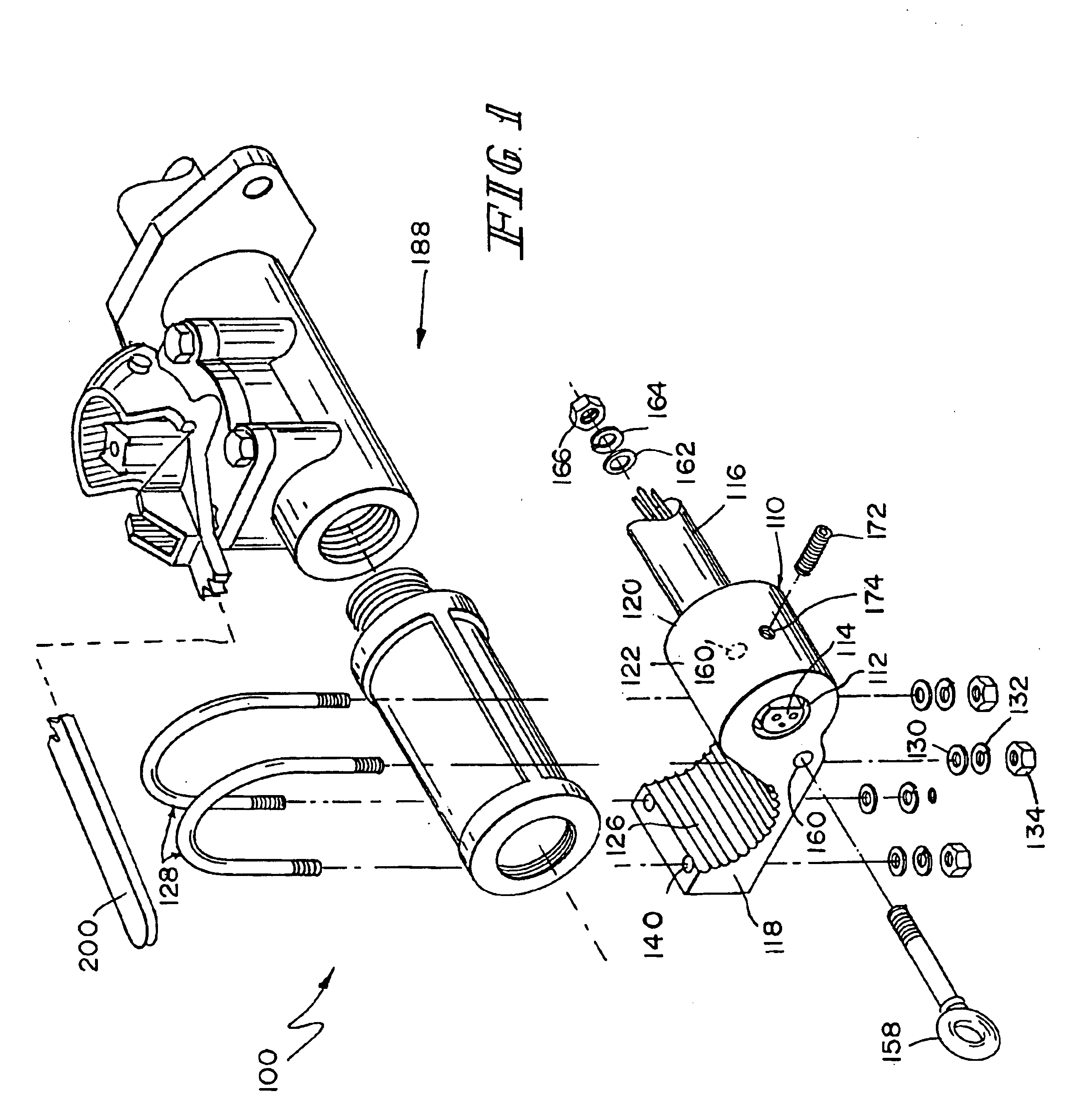
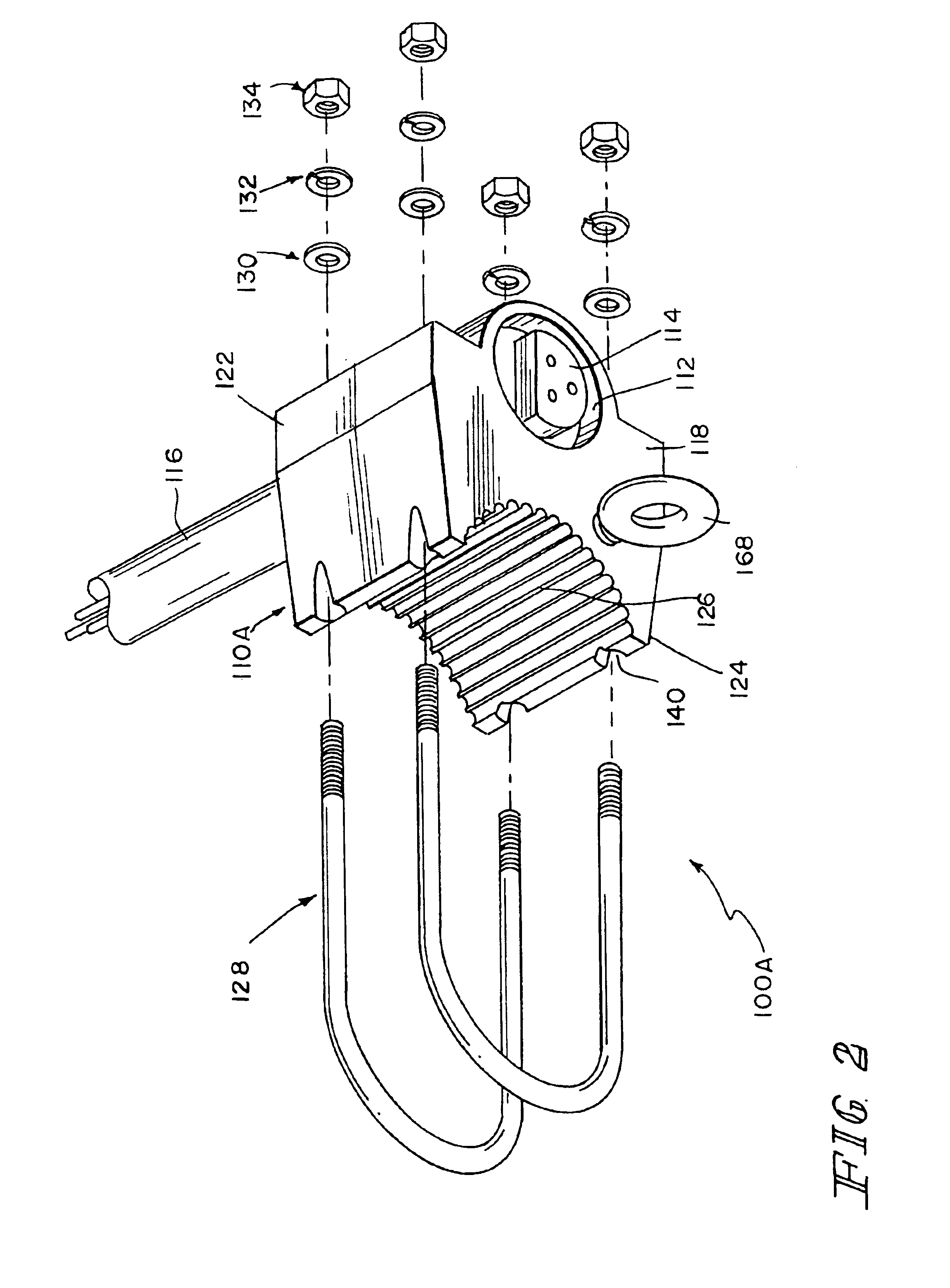
Generally, the mounting block assembly invention is comprised of a housing having a threaded hole that receives an electrical plug and electrical cable that is part of the electrical system that carries the electricity and communications from rail car to rail car through an entire train. The assembly also has a receiving means, in the form of a ring or hook, that is adapted to receive a connector such as a hook or clasp from a lanyard. The housing also has a securing means, which, in one embodiment, may be one or more U-bolts or a C-clamp that enable the housing to be secured, for example, around and to an air valve pipe. The air valve pipe, which is mounted at the end of each rail car, has an air hose connected to it. This combination of air valves and hoses on each rail car carries the compressed air that operate the train's brakes.

In another embodiment, the housing can also be secured to the end of a rail car by mounting it to a mounting plate on the rail car adjacent to the air ...


PUM


Abstract

A rail car mounting block assembly for electrical interconnections between railway cars. The assembly comprises a housing having a threaded opening therethrough adapted to receive an electrical plug and electrical cable. The assembly has a securing mechanism for attaching the housing to a rail car and the housing has a receiving means for receiving a connector of a lanyard. Further provided is a lanyard for supporting an electrical cable having electrical connectors at both ends and a combination of the lanyard and the electrical cable.

Description

BACKGROUND AND SUMMARY OF THE INVENTIONThe present invention relates to a rail car mounting block assembly for electrical interconnections between railway cars and to a lanyard for receiving an electrical cable with the lanyard connecting to the assembly. It also relates to the lanyard in combination with the cable.Today's railroad trains are equipped with air brakes and the trains' cars are provided with air brake pipes that terminate at the end of each rail car. The pipes have air hoses that connect to the pipes at the end of each car and extend or hang between each car. The combination of pipes and hoses carry compressed air to operate the brakes on each car. The flow of compressed air is controlled by valves mounted on the brake pipes at each end of each car. The air hoses that hang from each end-of-car brake pipe are joined between the cars by what is known as a “gladhand”. To prevent the hoses themselves and the gladhands from swaying too much or to prevent them from touching ...

Claims


Application Information

Patent Timeline
IPC IPC(8): B61G5/00B61G5/06H02G11/00
CPCH02G11/00B61G5/06
Inventor FLINT, KIP P.BURCH, JOHNNY L.TIMOUROU, GENE A.
Owner NEW YORK AIR BRAKE CORP
Why Eureka
Try Eureka