Hard bodied high capacity catch basin filtration system

a catch basin and hard body technology, applied in the direction of separation processes, sewage draining, ways, etc., can solve the problems of the installation and maintenance costs are high, and the fixed-dimension filtration system is therefore inability to account for the variance of the dimensions of the catch basin

Inactive Publication Date: 2005-03-29
OLDCASTLE PRECAST +1
View PDF48 Cites 63 Cited by
  • Summary
  • Abstract
  • Description
  • Claims
  • Application Information

AI Technical Summary

Benefits of technology

Another feature of this hard body embodiment is the addition of a secondary or ultimate high flow bypass that is substantially failsafe in the event of extreme fluid flows or failure of other components in the filtration system. This secondary high flow bypass comprises a spillover space around the upper edges of the upper body walls as the filtration system completely fills with fluid, since the entire system is lowered such that its upper edges are substantially below the inlet level of the catch basin. An adjustable deflector ring rests on an upper support surface of one or more support brackets, and is positioned substantially above the upper edges of the upper body walls such that the secondary high flow bypass is not impeded. This adjustable deflector ring is custom sized to fit within its particular catch basin such that the deflector ring substantially extends to all catch basin walls and thereby directs all incoming fluid into the filtration system below.

Problems solved by technology

However, these systems are also generally permanent installations that are expensive to install and maintain.
As various maintainable catch basin filtration systems for filtering storm water runoff have been developed additional problems have evolved.
An initial problem involves the installation of these systems in the wide variety of drain inlets and catch basins that currently exist.
Accordingly, fixed-dimension filtration systems are thus unable to account for variances in catch basin dimensions.
Moreover, because such filtration systems typically require regular maintenance, issues arise such as ease of access and the length of time that a system can operate between cleaning or replacing filter elements or other parts.
Access to elements that must be cleaned or replaced is problematic in some systems, such that a heightened burden is placed on those who regularly maintain these systems.
Another significant problem that has emerged in the development of catch basin filtration systems is the ability of such systems to process large quantities of fluid during peak flow periods without having backups or stoppages that result in localized flooding of surrounding areas.
As a result, these types of filtration systems have an upper limit for the amount of fluid that can be filtered at any given time as well as a maximum capacity for the amount of fluid that can be passed through the system in any event.
In practice, many catch basin filtration systems have proven to be inferior in one or both of these areas, with the result being that the filtering of storm water runoff is inadequate and / or that these systems become backed up and flood the surrounding local area.
As some filtration systems have attempted to overcome these problems by increasing the volume of the fluid retaining trough or reservoir in the filtration system, these systems have encountered problems in maintaining the shape of the reservoir during periods of high flow.
This then results in a backed up drainage system and localized flooding.
In addition, the high flow bypass in many current filtration systems is effectively unable to restrain large objects or “floatables,” such as cigarette butts, during high flow periods.
These objects typically pass through the filtration and drainage systems unimpeded whenever the high flow bypass is utilized in these systems.
Many cities, municipalities and other filtration system users prefer that any filtration system failure results in a loss of filtration rather than a clogging or backup in the system that could result in localized flooding.

Method used


Image

  • Hard bodied high capacity catch basin filtration system
  • Hard bodied high capacity catch basin filtration system
  • Hard bodied high capacity catch basin filtration system

Examples


Embodiment Construction

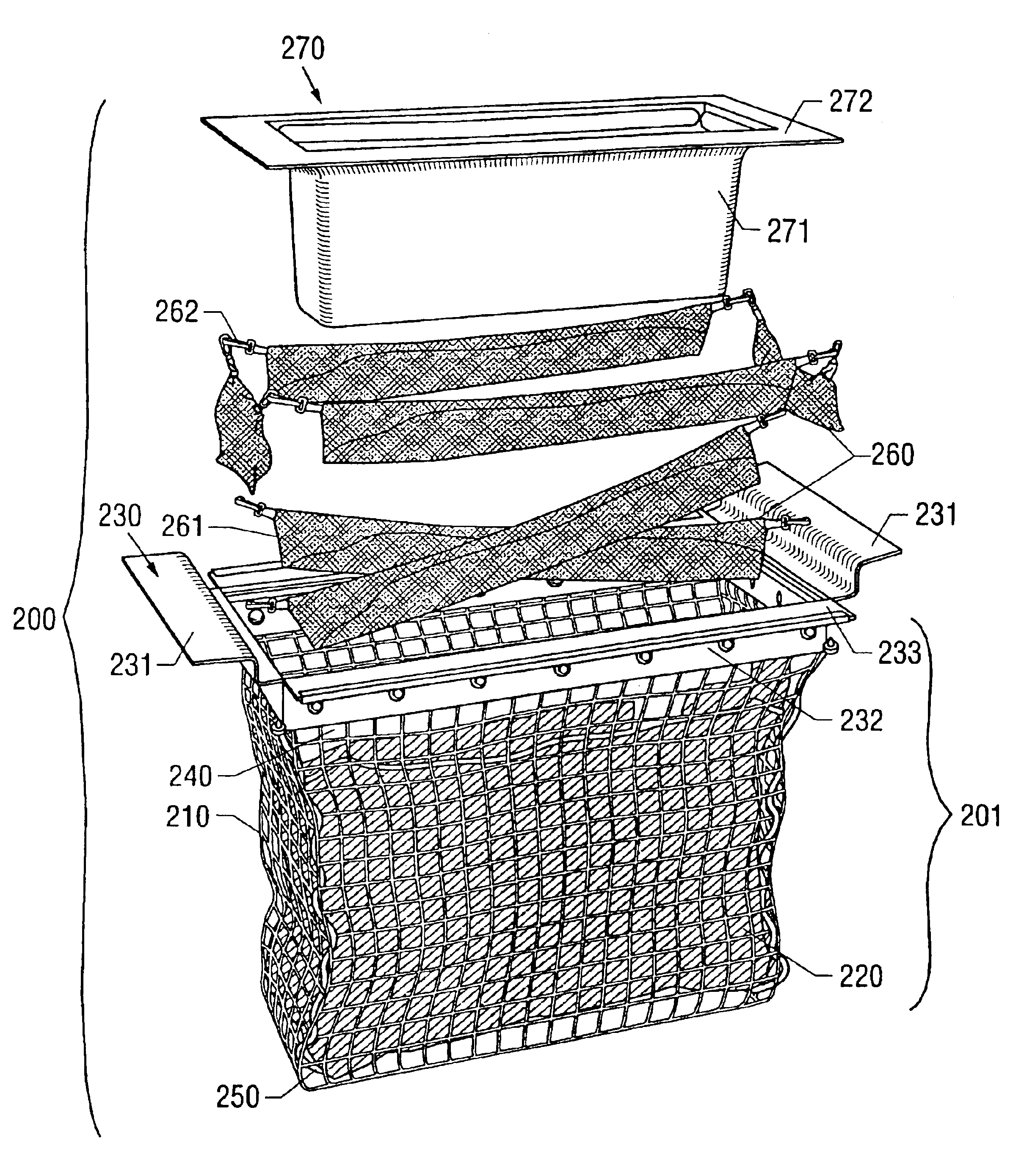
The present invention relates to drain inlets adapted to receive fluid flow or run-off. Such inlets take a variety of forms, for example curb openings, inlets or drains; drop inlets, combination inlets (e.g., curb inlets combined with drop inlets) and the like. Absent a barrier, fluid will flow unimpeded into the inlet and through the drainage system. Such drainage systems generally empty into a variety of geological formations such as bays, estuaries, rivers, lakes, or underground aquifers. The present invention is directed to a filter assembly that is easily cleaned and reused or easily removed and disposed of as circumstances warrant.

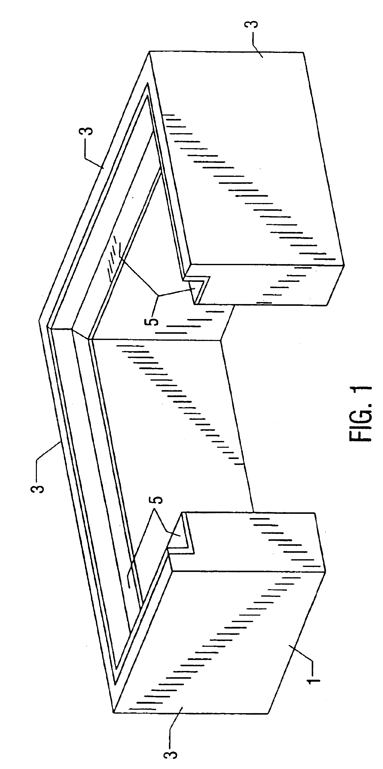
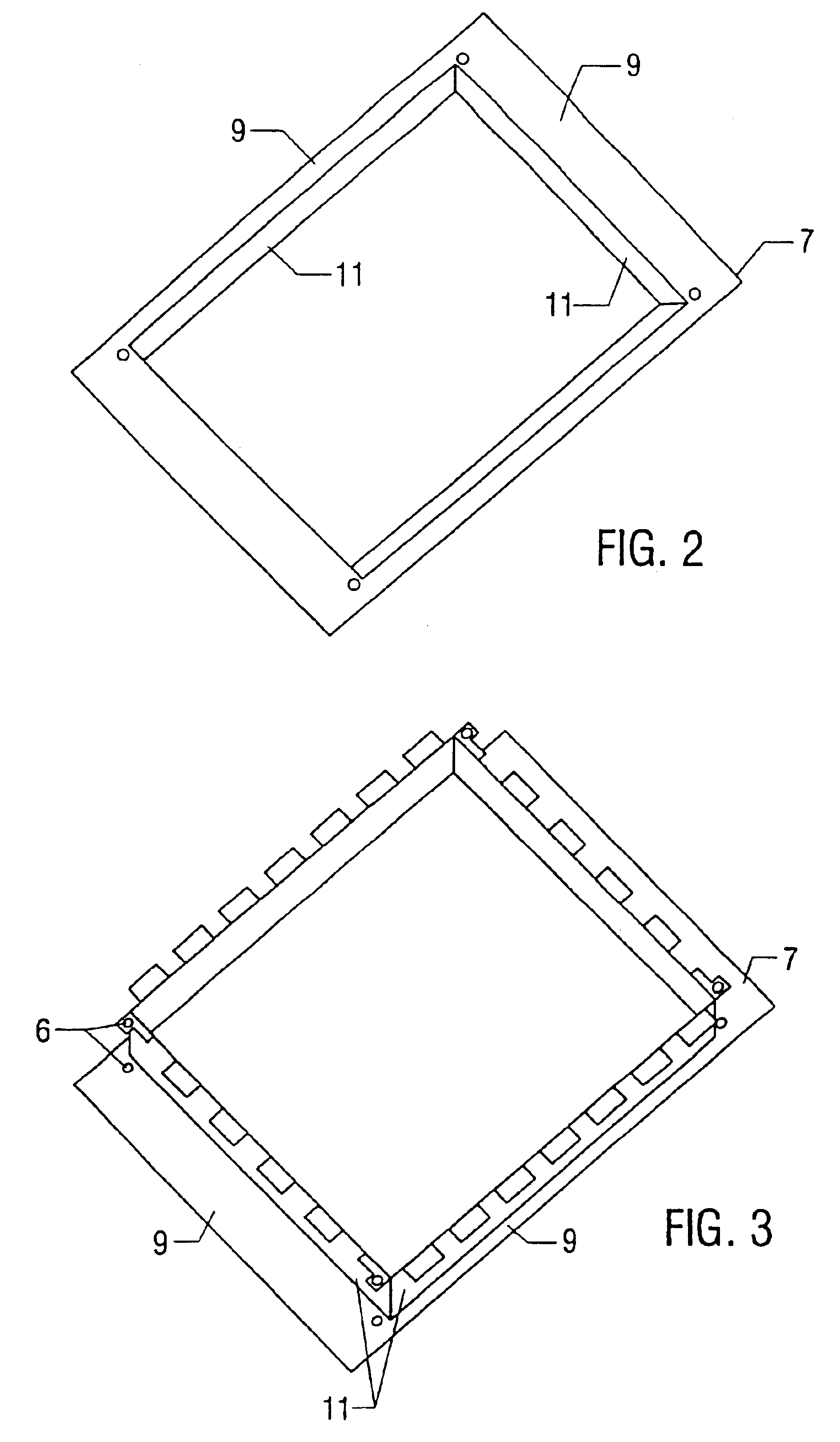
Generally, the present invention comprises a filter body supported by a filter body support. Generally the filter body support will comprise a frame from which the filter body is suspended. The frame is configured to support the filter body in the desired shape and position. In addition, the frame is configured to cooperatively engage with an inlet t...


PUM

PropertyMeasurementUnit
outer diameteraaaaaaaaaa
diameteraaaaaaaaaa

Abstract

A catch basin filtration system is disclosed. A filter body is dimensioned to fit within a drain inlet forming a trough or reservoir obstructing at least a portion of the inlet. The filter body is supported by a filter body support dimensioned to cooperatively engage with the interior walls of the inlet and with the filter body to substantially maintain said filter body in a pre-selected shape and position within the inlet. One or more connectors removably connect the filter body to the filter body support. One or more adjustable high fluid flow bypasses prevent the system from backing up and flooding surrounding areas during periods of high fluid flow.

Description

FIELD OF THE INVENTIONThe present invention relates generally to systems for filtering storm water runoff and specifically to drain inlets and structures for use in drain inlets to inhibit the flow of pollutants, debris and other contaminants into drainage systems.BACKGROUND OF THE INVENTIONDrainage systems for receiving fluid flow are well known in the art. Such systems provide a path for fluid flow from surface areas and often transport the fluid from surface areas directly to the ocean, rivers, lakes, estuaries, streams and the like without regard to the removal of debris, pollutants or other contaminants. For example, because of the Federal Environmental Protection Agency's Clean Water Act, controlling pollution from storm water runoff is receiving ever-increasing attention at all levels of government, Federal, State and local. Federal and state agencies have issued mandates and developed guidelines regarding the prevention of non-point source (storm water caused) pollution that...

Claims


Application Information

Patent Timeline
Patent Type & Authority Patents(United States)
IPC IPC(8): B01D29/27B01D29/13B01D35/00B01D35/05E03F1/00
CPCB01D29/27B01D35/05E03F1/00E03F5/0404B01D29/902B01D35/30B01D2201/48
Inventor ALLARD, DOUGLAS PAULWILSON, ANDREW CHARLES
Owner OLDCASTLE PRECAST
Why Eureka
Try Eureka