Catch basin filtration system will disposable silt/contaminant collector

a filtration system and catch basin technology, applied in the direction of sewage draining, separation processes, ways, etc., can solve the problems of high installation and maintenance costs, and achieve the effect of easy cleaning and maintenance of the filter body

Inactive Publication Date: 2005-12-20
OLDCASTLE PRECAST
View PDF39 Cites 32 Cited by
  • Summary
  • Abstract
  • Description
  • Claims
  • Application Information

AI Technical Summary

Benefits of technology

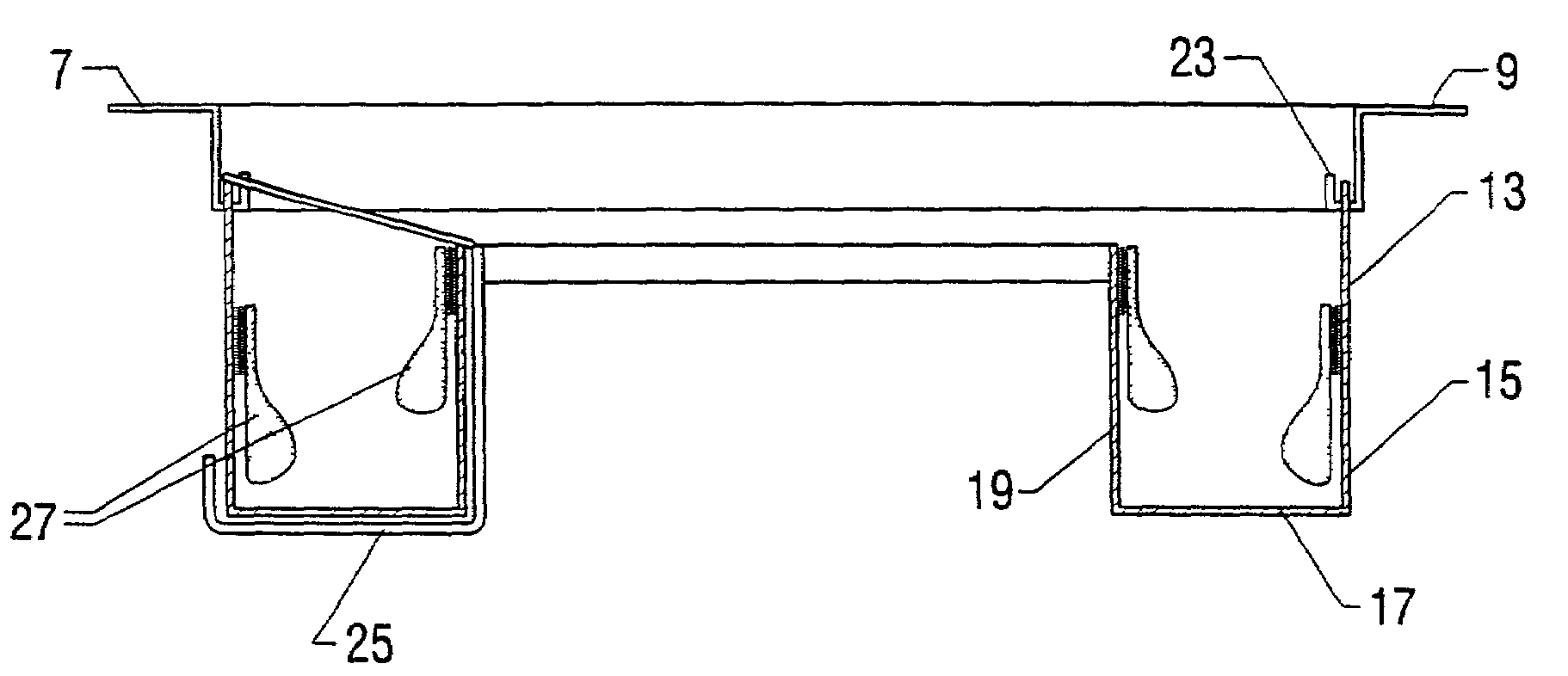
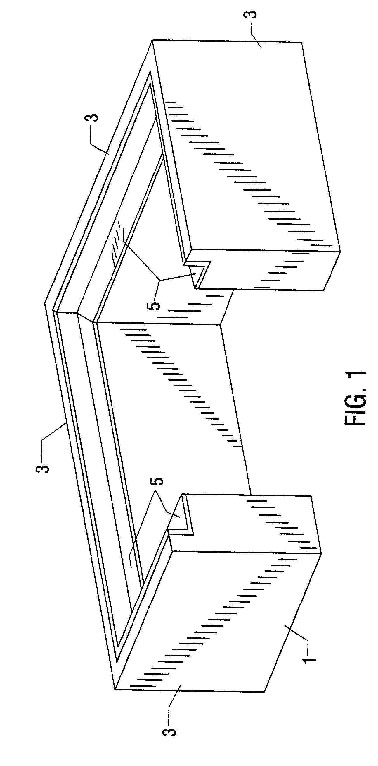
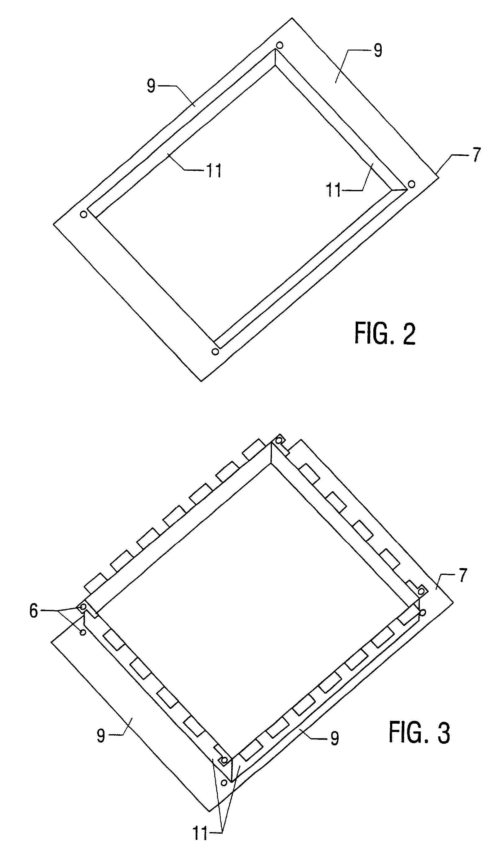
[0009]One feature of the present invention is the ability to easily remove the filter body, the adsorbent pouch, or both from the inlet. This provides the advantage of easily servicing the filtration system by removing the filter body or adsorbent pouches for cleaning or replacement.

Problems solved by technology

However, these systems are also generally permanent installations that are expensive to install and maintain.

Method used


Image

  • Catch basin filtration system will disposable silt/contaminant collector
  • Catch basin filtration system will disposable silt/contaminant collector
  • Catch basin filtration system will disposable silt/contaminant collector

Examples


Embodiment Construction

[0035]The present invention relates to drain inlets adapted to receive fluid flow or run-off. Such inlets take a variety of forms, for example curb openings, inlets or drains; drop inlets, combination inlets (e.g., curb inlets combined with drop inlets) and the like. Absent a barrier, fluid will flow unimpeded into the inlet and through the drainage system. Such drainage systems generally empty into a variety of geological formations such as bays, estuaries, rivers, lakes, or underground aquifers. The present invention is directed to a filter assembly that is easily cleaned and reused or easily removed and disposed of as circumstances warrant.

[0036]Generally, the present invention comprises a filter body supported by a filter body support. Generally the filter body support will comprise a frame from which the filter body is suspended. The frame is configured to support the filter body in the desired shape and position. In addition, the frame is configured to cooperatively engage wit...


PUM

PropertyMeasurementUnit
perimeteraaaaaaaaaa
shapeaaaaaaaaaa
surface areasaaaaaaaaaa

Abstract

A catch basin filtration system is disclosed. A filter body is dimensioned to fit within an drain inlet forming a trough obstructing at least a portion of the inlet. The filter body is supported by a filter body support dimensioned to cooperatively engage with the interior walls of the inlet and with the filter body to substantially maintain said filter body in a pre-selected shape and position within the inlet. One or more connectors removably connect the filter body to the filter body support.

Description

NOTICE OF PRIORTY[0001]The present application is a continuation of and claims priority from U.S. application Ser. No. 09 / 384,832, filed Aug. 27, 1999, now abandoned, which application is commonly assigned and which is hereby incorporated herein in its entirety by reference.FIELD OF THE INVENTION[0002]The present invention relates to drain inlets and structures for use in drain inlets to inhibit the flow of pollutants, debris and other contaminants into drainage systems.BACKGROUND OF THE INVENTION[0003]Drainage systems for receiving fluid flow are well known in the art. Such systems provide a path for fluid flow from surface areas and often transport the fluid from surface areas directly to the ocean, rivers, lakes, estuaries, streams and the like without regard to the removal of debris, pollutants or other contaminants. For example, because of the Federal Environmental Protection Agency's Clean Water Act, controlling pollution from storm water runoff is receiving ever-increasing at...

Claims


Application Information

Patent Timeline
Patent Type & Authority Patents(United States)
IPC IPC(8): B01D29/27B01D35/05E03F1/00
CPCB01D29/27B01D35/05E03F1/00E03F5/0404B01D29/902B01D35/30B01D2201/48
Inventor ALLARD, DOUGLAS PAUL
Owner OLDCASTLE PRECAST
Why Eureka
Try Eureka